I have joined the Pass ranks. I purchased a used Threshold S150. Impressive build and I am looking forward to a long association with this amp.
The main PS caps have been replaced, otherwise it is a stock unit. It is also a standard bias unit, not an optical bias type. After a few hours of warming, the bias on left channel was 65mv, right 45mv. Dc offset was under 15mv on both channels. The original owner had not ever made any adjustments. With these setting, the left channel was only slightly warm, the right basically ambient. I set out to rebias the amp to a higher level. First up to 100mv on each channel and let it run for a few hours. Rechecked and found the bias has settled back to 65mv on each channel. I again raised the bias to 130mv, and after a few hours checked the bias at 100mv and the heat sink temp was aroung 105 F. The offset increased to around 24mv on each channel. I guess that there is still upside adjustment to reach the optimum operating level using the 10 sec touch rule. Then I turned the unit off for the evening.
Today I found a paper on the factory bias procedure, explaining the factory bias scheme. It indicates that the cold startup bias should be set for 180mv. I assume that is the peak reading that should be seen upon start up. I monitored the bias reading as I started the unit up cold and it exceeded the 180mv level, so I switched it off.
My question is this; If I plan to switch off the unit and not run it 24/7, should the bias be set to not exceed the 180mv level and accept the under optimum bias level? Am I being overly cautious?
Also, there are no Tantalum caps on this unit to be replaced, but there is two 4.7uf electros on each channel that are original. I guess that the recommendation would be to replace them. What is their purpose, and what is to be gained by their replacement?
Thanks...
pretty much Papatime
though , I would say - bias it to what you want in temp equilibrium and do not worry for initial Iq , as long you have proper output offset
caps - just replace them
for whatever they are , they're old now
though , I would say - bias it to what you want in temp equilibrium and do not worry for initial Iq , as long you have proper output offset
caps - just replace them
for whatever they are , they're old now
Hope Papa is around. Also there is some swing in the mains(118 to 124vac) as there is a ski resort down the way with start/stop lifts. I have desided that it would be safer to not ride the proverbial bias edge because of this. Not looking forward to disassembling the new to me amp to change those two caps.
The 180 mV figure is probably the factory's initial setup, to be adjusted
again after the amp warms up, and then readjusted again. As long as
the bias tracks down as the temperature rises and settles in with heat sinks
following the 10 second rule, you should be good.
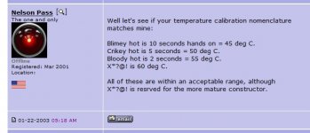
Somewhere between Blimey and Crikey.
Electrolytic caps dry out over the years. It won't hurt to replace them.
again after the amp warms up, and then readjusted again. As long as
the bias tracks down as the temperature rises and settles in with heat sinks
following the 10 second rule, you should be good.
Somewhere between Blimey and Crikey.
Electrolytic caps dry out over the years. It won't hurt to replace them.
Attachments
Thanks for that advise. Being an older gentleman without much feeling in the ends of my fingers, the scale maybe a bit skewed. I'll inlist my wife's help.
Thanks again.
Thanks again.
IR thermometers are cheap these days, and read most accurately
off the black surface of the heat sink.
off the black surface of the heat sink.
Harbor Freight is your friend. Bring a coupon and get it for even less.
Search results for: 'infrared therm'
Non-Contact Infrared Thermometer With Laser Targeting
Search results for: 'infrared therm'
Non-Contact Infrared Thermometer With Laser Targeting
Hello dear friends, I came to seek help from you.
I have a Threshould S150 MK1. I would like to know what is the procedure to adjust the bias. I open it and inside in see no potentiometer or variable resistor for adjustment. Where to measure the voltage?
Another issue I have is on power up there I hear slope noise. Is this common for the S150 or it is something to be worried about? I'm afraid it would not be very healthy for the speakers with continue use.
Thanks for your help!
Hello.
Thanks for the pdf file.
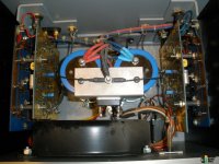
Here are the pictures of the interior. I'm unable to find the points for calibration indicated in the manual.
My amp sounds great to me but I think it is under biased as it is much colder than indicated in the manual. Temperature should be about 42 to 49 ºC but it is not hotter than 30 ºC.
Can anyone help?
Thanks
Thanks for the pdf file.
Here are the pictures of the interior. I'm unable to find the points for calibration indicated in the manual.
My amp sounds great to me but I think it is under biased as it is much colder than indicated in the manual. Temperature should be about 42 to 49 ºC but it is not hotter than 30 ºC.
Can anyone help?
Thanks
Attachments
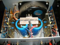
I see blue trimpots
you think you're capable of doing biasing procedure , if you aren't able to recognize trimpots ?
not belittling you , just saying that's maybe better to leave that operation to someone more experienced in electronics .......
also , it would be clever to check condition of all small electrolytic caps on pcbs , and replace them with new ones
be careful with that Jewel , it deserves it
I was already able to find the 1ohm resistor in which to measure the voltage and to adjust it with the blue pot. However it is very difficult to use the method described in the pdf file by measuring the initial voltage. I would rather use the stable voltage. At moment I've settled around 50 mV stable and the aluminum heat dissipators are already warm. I should say around 37ºC. Is this a goo setting, or is it still low?
you have all necessary information about temperature in posted pdf file
however , you can always set it colder , if you choose
however , you can always set it colder , if you choose
Thanks Zen Mod! I think I will opt for a colder setting to be on the safe side.
Can you also tell me if it's normal to hear a pop sound on power-on with these amplifiers?
Can you also tell me if it's normal to hear a pop sound on power-on with these amplifiers?
pop sound is pretty normal for many amps , best is to observe bass cone - it can jump a little , but not abrupt
however , I can bet - when you change all old electrolytics on channel pcbs , pop will be either massively reduced or vanish
however , I can bet - when you change all old electrolytics on channel pcbs , pop will be either massively reduced or vanish
- Home
- Amplifiers
- Pass Labs
- Threshold biasing?