Mallory 9800uF 100V caps coming in at ~10k Uf. With around 40mOhms esr. Seem to be holding up well so i will keep these.

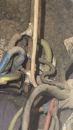
Plan was to remove power cord and replace with plug in polarized plug. I noticed a stressed component tied across the AC power lines.
400V 0.10 +/- 20 GE.
I assume this is a suppression cap? Its encased in a plastic housing. It was busted in two pieces


This is with power cord removed.

400V 0.10 +/- 20 GE.
I assume this is a suppression cap? Its encased in a plastic housing. It was busted in two pieces
This is with power cord removed.
Attachments
Cleaning up back portion of power supply i found a 1N4004 diode and a 470uF/35V cap. This appears be be a supply and filter cap for front display board. I didn’t like the cap glued in the back; it was also out of spec, I replaced and moved to front display board.


Additional pics of area:


Additional pics of area:
Last edited:
Question on the power on switch. Is the HOT side of the AC power line being fed into the power on Switch? What snubber cap is used on the
power switch? I this 0.1uF/400V cap? or is it and RC network.
On this unit the Neutral line from AC power line is tied to the "black" lead going directly into the Xfmer.
=============== {------{-------Neutral------------------------------------Black Lead to Xfer
==========AC PLug { {
=============== { ----{ -----HOT----------------power switch--------White Lead to Xfmer

Thanks for reply. Whats throwing me off is the black and white inputs to the transformer. On this model the Heinemann switch is on the opposite side. Is this correct? I know it will work but it seems backwards. Literally.

Correct no center tap. So black and white are interchangeable as far as flow.primary wire colors are irrelevant, in this case
you don't have secondary centertap drawn?
I always assumed the hot side of the AC plug would be tied to switch. Unless maybe a Triac would be used to limit the arcing on the power switch.
I always assumed the hot side of the AC plug would be tied to switch.
that's correct, thinking of your protection
now, neither mains, nor switch nor xformer care about that
starting with - it's called Alternating Current, so no actual polarity
is it neutral or live, that's just how it is organized in human world, for humans safety sake
Agreed on mr xfmer not having feelings. But I guess thats why they call it a polarized plug. It makes my primate brain feel better that i am not reversing polarity and my chassis is tied to earth ground.
again, it's "polarized" for your safety
in sort of way, we all are walking on Neutral
we can have myriad of different "Live"-s around and - as long they're isolated from Neutral and from us (and the other way) we are happy to still mingle around
in sort of way, we all are walking on Neutral
we can have myriad of different "Live"-s around and - as long they're isolated from Neutral and from us (and the other way) we are happy to still mingle around
I would agree but i still don’t mingle without proper “protection “. Safety first or risk a shocker.
Off to the amps I must go.
Off to the amps I must go.
The mains switch/CB should be switching the hot side of the AC mains supply. The transformer primary colors being black and white can be wired either way around. Your transformer there has the white wire to hot and in the schematic I posted for the 4000 amp the hot is connected to the black primary wire.
Not sure how your 120VAC mains is wired in the US, but here in Australia with our 240VAC mains the neutral is connected to earth at the supply board at every house ( this is the MEN system - being Multiple Earth Neutral) - so you will always read 0VAC between the neutral wire and earth and 240VAC between active (hot) and earth or neutral - so it is easy here to always know what wire from the mains is hot.
Make sure the mains caps C1 and C2 if you are installing new ones are suitably rated for mains voltage connection.
Make sure the mains caps C1 and C2 if you are installing new ones are suitably rated for mains voltage connection.
Thanks for the feedback and i always only thought the toilets flowed in the reverse direction. Knowing all to well that its a myth.
Yes C2 was smoked, so a properly rated cap to reduce or take away current from the switch contacts(arcing) is in order. Don’t know how long this unit has been running without snubber, I suspect its been while.
Regards
That would be like C1 in this schematic from a 4000 Threshold power supply - wired across the mains switch or CB.
Thanks for dropping the 4000 PS schematic, It's a different animal with 2 banks of main PS caps, 400A only has 1bank and 1 bridge rectifier. Adding the extra heat sink length and more output transistors gave them space to add 2 more caps and another bridge, so they went for it.
Pete
The fact that one cap went away, probably didnt hurt anything, as, believe it or not, putting a snubber across the load after the switch serves the same function as putting it across the switch, and since you had one of each, the one across the transformer leads snubbed acceptably. In fact, I dont like ne across the switch, as it will leak a small amount of current through it (only 452microAmps, but its still something) all of the time it is plugged in, as well as take any voltage surge hits while it is plugged in, even if the unit is switched off. You do need to replace those with X-Y rated caps though, as they will not internally short out and cause major issues over time. They are described as "self-healing" , but in actuality they are designed to incrementally vaporize a small amount of internal foil in them every time they are pushed past a rated voltage, ( Dave at EEVBlog on Youtube unwound one and showed the incremental damage that occurs over time on a faulty X-Y rated cap) slowly reducing the capacitance, but should never short internally and cause issues. I would consider just using 1 - 0.022uF, X-Y rated cap, and putting it only across the transformers Black and White primary leads. One thing I dont see on your amp that I have, is a larger, about a 2 watt carbon comp resistor being used as a dropping resistor , on the terminal strip you have the cap and diode on, for the display panel power. I didnt verify it, but I think my transformers secondary doesnt have that Blue-Black wire tap for a lower volt output, and they just used a resistive dropper off of the main rail. I havent really tore into mine, but I will share notes once I do, I just need to create a nice work space in my shop to go forward doing so.
The fact that one cap went away, probably didnt hurt anything, as, believe it or not, putting a snubber across the load after the switch serves the same function as putting it across the switch, and since you had one of each, the one across the transformer leads snubbed acceptably. In fact, I dont like ne across the switch, as it will leak a small amount of current through it (only 452microAmps, but its still something) all of the time it is plugged in, as well as take any voltage surge hits while it is plugged in, even if the unit is switched off. You do need to replace those with X-Y rated caps though, as they will not internally short out and cause major issues over time. They are described as "self-healing" , but in actuality they are designed to incrementally vaporize a small amount of internal foil in them every time they are pushed past a rated voltage, ( Dave at EEVBlog on Youtube unwound one and showed the incremental damage that occurs over time on a faulty X-Y rated cap) slowly reducing the capacitance, but should never short internally and cause issues. I would consider just using 1 - 0.022uF, X-Y rated cap, and putting it only across the transformers Black and White primary leads. One thing I dont see on your amp that I have, is a larger, about a 2 watt carbon comp resistor being used as a dropping resistor , on the terminal strip you have the cap and diode on, for the display panel power. I didnt verify it, but I think my transformers secondary doesnt have that Blue-Black wire tap for a lower volt output, and they just used a resistive dropper off of the main rail. I havent really tore into mine, but I will share notes once I do, I just need to create a nice work space in my shop to go forward doing so.
Common standard for US AC line power wiring is "Black - HOT / White - NEUTRAL". You dont show it connected on your schematic, but your secondary should have the "Blue/White" wire connected to chassis ground as well, as it's the zero volt point for the 2 - "BLUE" secondary leads to create your voltage for the main PS rectifier bridge.Thanks for reply. Whats throwing me off is the black and white inputs to the transformer. On this model the Heinemann switch is on the opposite side. Is this correct? I know it will work but it seems backwards. Literally.
View attachment 1423343
Common standard for US AC line power wiring is "Black - HOT / White - NEUTRAL". You dont show it connected on your schematic, but your secondary should have the "Blue/White" wire
I like your thinking. Yes the secondary blue white is gnd in this configuration. The blue/black sets up the ~22V panel display voltage.
As far as the snubber across the AC line fortunately it crapped out as an open. There is still a 0.01uf across the AirPax switch.


I have some Panasonic Safety Caps in the 10,000pF range 1.2kV i may drop in for grins.
This unit has been a doorstop for quite some time by the looks of it. Just trying to clean it up. Off to the right channel driver board.👍
Putting the cap back ….oddly enough a second set of holes for the cap bracket had been drilled into base of unit. I can only assume it was done to fit the precut Aluminum ground bracket.

Post reinstall. Thinking anout adding a non inductive bypass cap across mains as well as a bleed res. I have some 6.8k 3W. Which should do the trick.
~0.5 Watt.

.
Post reinstall. Thinking anout adding a non inductive bypass cap across mains as well as a bleed res. I have some 6.8k 3W. Which should do the trick.
~0.5 Watt.
.
Last edited:
- Home
- Amplifiers
- Pass Labs
- Threshold 400A. L/R Channel out and fix