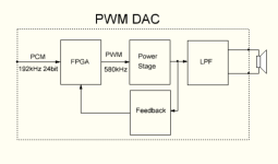
If during the production of active speakers there is not enough 200W to organize the low-frequency channel, then the necessary power for the low frequencies will be higher than 200W, which means that the fourth channel will not fit into this module in any way. However, the solution to the problem is quite simple: you just need to use an external module for the subwoofer that has an optical input or SPDIF input. Modules for active speakers allow transmitting signals via SPDIF, both from DSP and directly bypassing DSP.Ideally with 4th output for a subwoofer amp.
I've made a light version of the three-channel DAC board with ADAU1452, delivering 100W per channel at 32V power supply and 4Ω load.
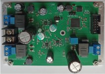
Additional modules are available for the board, featuring optical SPDIF input and output, as well as coaxial SPDIF input and output.
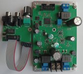
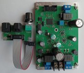
If you don't require 100W per channel, the boards can be powered with lower voltage. However, you'll need to proportionally decrease the channel gain in the DSP settings to avoid clipping the output signal at maximum volume.
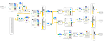
The ADAU is configured for stereo output with a third low-frequency channel according to this scheme.
For those interested in using such boards in active speakers, they can be ordered on eBay or by contacting me through this website. Ordering directly will offer a 10% discount. Currently, only two boards are available.
Board
Coaxial In/Out
Optical In/Out

Additional modules are available for the board, featuring optical SPDIF input and output, as well as coaxial SPDIF input and output.


If you don't require 100W per channel, the boards can be powered with lower voltage. However, you'll need to proportionally decrease the channel gain in the DSP settings to avoid clipping the output signal at maximum volume.
The ADAU is configured for stereo output with a third low-frequency channel according to this scheme.

For those interested in using such boards in active speakers, they can be ordered on eBay or by contacting me through this website. Ordering directly will offer a 10% discount. Currently, only two boards are available.
Board
Coaxial In/Out
Optical In/Out
Interesting! Questions:
Thanks
- Can the DSP can be programmed via SigmaStudio using the 3 terminal I2C connector and a standard USBi programmer?
- Are heatsinks recommended/required on the 3 chips on the bottom of the board?
- What did you use for a power supply?
Thanks
Of course, yes.an the DSP can be programmed via SigmaStudio using the 3 terminal I2C connector and a standard USBi programmer?
The schematic indicates that the board implements an I2C port specifically for programming the ADAU1452.
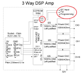
The DSP has been programmed with a basic project firmware to verify the board's parameters. I also provide this project in SigmaStudio file format upon request via email, as it contains all the DSP settings necessary to synchronize the DSP with the board. Without these settings, creating a new project would be quite problematic, as it requires knowledge of certain settings such as the board's clock frequency, etc.
When supplying the board with a 32V power voltage, an additional heatsink is required. The total power consumption of the entire board at 32V power supply ranges from 9W to 11W, depending on the temperature of the heatsink. By default, the board is mounted on a plate heatsink with sufficient effective area, which is only enough when the board is powered up to 20V. Beyond 20V, an additional heatsink is necessary. If there's no actual need for 100W per channel, it's optimal to apply a lower power supply voltage to reduce the board's power consumption.Are heatsinks recommended/required on the 3 chips on the bottom of the board?
I use switching regulated power supplies, including flyback converters or push-pull power supply. The board isn't overly demanding in terms of power source quality since it has local voltage regulators. The main thing is to avoid using extremely poor power sources that generate significant noise and can't sustain the required peak output current.What did you use for a power supply?
Please note that to achieve an average power of 100W per channel, the power supply must deliver a peak current of 18.75A. This is a lot, and not every power supply can withstand such current. However, this is not always necessary. If the board is used in active speakers, the main power will be distributed to only one channel, reducing the peak power consumption of the power supply by three times.
Regarding the heatsink: do those 3 chips stand higher than the the other components so a single plate heatsink could be used to cover all three? Or is a separate, smaller heatsink required for each chip?
Take a close look at the photos I showed earlier; the board is already mounted on a plate heatsink. This plate heatsink has holes at the corners, allowing it to be attached to a larger heatsink if desired. You can remove the board from the basic plate heatsink, and attach it to another larger plate heatsink. To increase the distance between the power chips and the plate heatsink aluminum heat conductors, 3mm in height, are used to achieve this. Thus, using heat conductors, the board is lifted 3.5mm away from the heatsink, ensuring that surface mount components have the necessary air gap from the heatsink.Regarding the heatsink: do those 3 chips stand higher than the the other components so a single plate heatsink could be used to cover all three? Or is a separate, smaller heatsink required for each chip?
Hi, I’ve been looking around for a 1452 board after having done several projects with the 1701. I just found this thread this morning and subscribed and then your post with the light version came up. I’ve bought a board to evaluate and look forward to letting you know how I get on.
I'm sitting right now registering a parcel to your address. I hope I can send it to the address you provided tomorrow.Hi, I’ve been looking around for a 1452 board after having done several projects with the 1701. I just found this thread this morning and subscribed and then your post with the light version came up. I’ve bought a board to evaluate and look forward to letting you know how I get on.
In this thread I will post a project in Sigma Studio for this version of the board, you need it to create new projects, download it for yourself and use its hardware settings as the basis for your new projects. If you have any questions about the board, ask them here and I will answer.
Attachments
I created a separate thread on the light version of the 3Way DAC.
https://www.diyaudio.com/community/...dau1452-100w-per-channel.410804/#post-7639659
https://www.diyaudio.com/community/...dau1452-100w-per-channel.410804/#post-7639659
- Home
- Source & Line
- Digital Line Level
- Three-way powerful PWM DAC with DSP ADAU1452, for implementation active speakers
