Hi all,
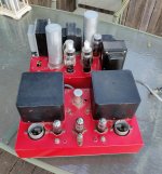
I picked this up today for the same price that was marked on one of the spare tube boxes. Those OPTs are hefty. I pulled the cover off and discovered a transformer underneath that is indeed that big, but potted in wax. As you can see, the PS is quite a mash mash of vintage stuff. Haven't seen many pairs of 3B28s. The HV supply is on a mechanical timer.
Based on a quick look (you folks know better than I) I see a half 6sn7 to the grid of half a 5687 to the grid of a 6sn7 strapped in parallel to the grid of the 845. A quick google suggests you don't see that topology every day either.
There are a bunch of receipts in the bag for repairs spanning 2005-2013. (The owner at that time, I think the second, paid $240 for a shop to build an umbilical terminated with electrical tape!). It evidently worked when sold to the third owner; a solder joint broke during transit; some idiot popped an 8sn7 into one of the holes; it didn't work; and then on the way to the shop he stopped fast and broke the power tubes. So he sold it to me. But the point is that it appears to have run for quite awhile and been modified and updated from time to time.
I know this topology isn't ideal. I also know the soldering is scary bad. (Folks say my builds aren't pretty or terribly safe, but at least I'm better than this!) I don't have time right now to re-engineer the entire thing. But, I could certainly clean up the bad joints; replace the scariest bits; toss in some cheap 845s; and if it powers up nicely (I've got a variac and isolation transformer and know how to do that), see if it works. (I also don't love the safety earth through the umbilical, thoughts?)
Is that a terrible idea? I know it needs a better topology to make more power. And that I'd be better off with a simpler 300B amp. But boy would it be a cool looking and heat-wasting way to make music!
Paul
Attachments
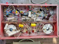
Here is the PS. I think, per the receipts, a shop rewired all of this. Doesn't seem like professional work ....
I'm not too much into buying tube amps these days. But I spent a week locked in the basement with COVID (*joke about country of origin deleted*) allowing me to find all sorts of fun stuff I wanted to buy.
Paul
I'm not too much into buying tube amps these days. But I spent a week locked in the basement with COVID (*joke about country of origin deleted*) allowing me to find all sorts of fun stuff I wanted to buy.
Paul
Attachments

Last edited:
Have any sort of schematic?
Also know what you want to drive with it?
Looks like it could be a fairly nice amp but you need to know a bit more about it.
I have an 845 amplifier driving horns from 400hz up as my daily driver.
Not configured as high power though.
I am in Denver BTW.
Also know what you want to drive with it?
Looks like it could be a fairly nice amp but you need to know a bit more about it.
I have an 845 amplifier driving horns from 400hz up as my daily driver.
Not configured as high power though.
I am in Denver BTW.
No schematic. Don't particularly want to draw one.
I can drive it with a 5687 WOT pre. Plenty for most things, given that my speakers are sensitive-ish. I have a B1 buffer if they've got too much gain. And with four gain stages, I'm guessing there is some gain here.
Paul
I can drive it with a 5687 WOT pre. Plenty for most things, given that my speakers are sensitive-ish. I have a B1 buffer if they've got too much gain. And with four gain stages, I'm guessing there is some gain here.
Paul
Update: signal side looks Music Angel-like. Just with way more power supply and output transformer. SET triode amplifier Music Angel 845 Hong Kong
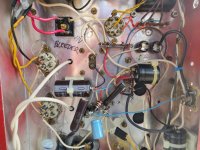
One of those crimp on wire nuts on the top right looks to be discolored from heat. Personally I would strip out that rats nest and do a rebuild.
No HV bleeder... nice. I would just strip it and rebuild it like you want it. That takes about as much time as troubleshooting this mess and you can build it to your own safety requirements
One of those crimp on wire nuts on the top right looks to be discolored from heat. Personally I would strip out that rats nest and do a rebuild.
See all those holes drilled around it? Those were drilled later--sloppily and after paint. So they knew it was a problem. Those two wires are melted together, so one of the things I'd clean up before firing up.
As far as rebuilding--no question that is the right way to go. But, unlike my homemade SS amps, my tube stuff has a tendency to always end up noisy or misbehaving in some way. What if this one works as is? I gotta' find out before destroying it.
Plus, as my wife points out, I'm sentimental. Somebody poured their heart into this for years. I'd like to see if it works in part because I'd feel bad finding one of the diy tube amps I built and sold cheap having been gutted without ever being tried.
Paul
No HV bleeder... nice.
Isn't that neat? At least they warn you! How hard is it to add a safety bleeder?
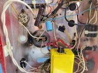
Not a ton of power supply capacitance here. They used big old oil filed AC caps on top. The one that is labeled says 45mf 600VAC. The other one is missing its label, but the same size. Given that the HV parts are generally rated around 1000V, I'm hoping they kept the HV down around 800V. Only one way to find out ....
The 'lytics in the signal chassis are in the filament supply of the 845s. The smaller can on top the PS looks like a 'lytic to me, 4mf at 600VDC. Filament supply?
There's the chance here that because the previous bozo attempted to fire it up with a broken solder joint, a wrong tube, and whatever else, some aspect of the power supply is fried. If so, I don't think it'd be worth restoring as-is.
I suppose my bigger decision is just figuring out whether it is worth it to pony up for a pair of 845s to see if it works or whether to put it on the shelf for ... a decade or two.
Paul
One other structural concern: the chassis is a little light for the OPTs, so it is bowing. The tag board, as you can see, is bolted the full length of the chassis, suggesting to me it is taking some significant strain. I really don't like that fiber being pressed into duty as a structural element, but for all I know, it can take some flex before problems arise. Opinions welcome.
Another big reason I put this thread up is to see if anybody recognizes those OPTs. If I were rebuilding, it would be pretty useful to know what they are and see if I can dig up a datasheet.
Paul
Another big reason I put this thread up is to see if anybody recognizes those OPTs. If I were rebuilding, it would be pretty useful to know what they are and see if I can dig up a datasheet.
Paul
I get the sentimental part but you have some sketchy things going on ranging from shoddy solderjoints, someone who was okay with writing that there is no HV bleeder instead of just adding one, some structural issues and having to reverse engineer the whole thing.
Don't take risks, honour the original builder by turning it into what it should have been 🙂
Don't take risks, honour the original builder by turning it into what it should have been 🙂
If I were rebuilding, I'd want mono blocks with the PS on board each (I know they'd be big). I'd probably go with TubeLab's 845 SE. But that'd take a huge investment in time, and quite a bit in PS parts. Really, the only things I'd save are the OPTs and big sockets.
Still planning to fire this up and see what I've got. Trying to decide if I'm patient enough to await 845s from overseas (and the chance they arrive broken).
Paul
Still planning to fire this up and see what I've got. Trying to decide if I'm patient enough to await 845s from overseas (and the chance they arrive broken).
Paul
Member
Joined 2009
Paid Member
I would suggest, from a safety standpoint that it would be a good idea to draw the schematic when you clean up and test it so you know what you you are doing
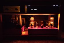
And now reborn!
I never got the old circuit to stop oscillating. I found a circuit here that seemed like a good fit for the PS and chassis layout I had to work with. After waiting weeks for USPS to lose and find parts again, and after some great help from the extremely generous Grover, it is alive and working well!
A little more hum than I'd like, but I've never had a truly quiet tube device, even with commercial kits. B+ ended up at 875ish, and biased at 80-85 ma, it is giving me a touch over 20 watts into 4, 8, and 16 ohms from the respective taps before visible clipping on the scope. Starts to roll off between 20-30hz on the bottom and above 23khz at full power.
Vocals are very compelling. It isn't as open and relaxed as the DIY First Watt F5 monos, but it needs some time and some tube rolling, perhaps. (Going to swap to 6L6 variants as even with only a buffer, it is much more gain than I need, clipping at 1.3-1.4V input.). The bass is more fun than the F5s!
Paul
Attachments
Nice that you stuck with it and did the best you could under the circumstances. Always good to have help. Looks great. Bill
Member
Joined 2009
Paid Member
The glow is crazy! I'm looking at some nicer 845s. I literally plugged in the cheapest ones I could find (like $80 for the pair) because I didn't know if I'd get it working. (One of the bayonets has since popped off!) Some of the new 845s have windows cut so there is even more glow!
One thing I really enjoyed about building this is having PLENTY of room in the chassis for Grover's simple circuit. Perhaps inspired by finding this forum back when Peter Daniel chip amps were all the rage, I've always tried to make stuff super small (even my previous two chassis tube amp and especially my current F5 monoblocks), which creates difficulty. This was easy with that enormous turret board!
Paul
- Home
- Amplifiers
- Tubes / Valves
- Thoughts re: Unusual 845 amp