The 750pF cap is probably not appropriate for this output transformer. If you look at the 912 schematic, they use 1000pF across each half of the primary. That might be a place to start.
The filter network I circled in #6 is a low-pass filter across the plate resistor of the EF86. It may or may not work with your OPTs. It could be fine, or it might exacerbate whatever high-frequency phase shifts the OPTs are prone to with feedback.
Like artosalo says, when you are "shooting from the hip" with a feedback amplifier, you start with the feedback resistor in place, observe a 10kHz square wave at 1 watt, and apply a phase-lead cap across the feedback resistor to tame any excessive overshoot on the leading edge. Then if necessary, you add the low-pass filter to the first stage of the amp to further reduce overshoot and flatten any ripples along the top of the square wave. If things look good, then you dab a .047uF cap across the load on the output. If the square wave holds, the amp is fairly stable. If it collapses into random noise, the amp might be prone to oscillate above the audio range, which is not good. You could start with what they have on the schematic, but be aware that it might make matters worse than better.
If the amp is stable with .047uF across the load, the larger goal then is to increase the capacitance across the load until the square wave collapses. If you can get up to .22uF, that's a pretty stable amp. That may call for adjusting both the low-pass filter and the phase lead cap. You can go even further by testing the amp with no load, or a capacitance only load. Getting an amp to pass those tests calls for some real expertise.
Phase shifts above the audio band are tricky. Real engineers (not me!) use various scope tests to pinpoint the phase shifts that cause oscillation, then do the math to design compensation networks that increase the phase margins at those points and stabilize the amp. Those of us with lesser skills have to "hunt and peck." ;-)
In my Williamsons I use a pretty agressive low-pass filter (1200pF + 1800 ohms in series) and a cap across the feedback resistor. The amps are stable unloaded, with .22uF across an 8-ohm load, and into a .01uF capacitor-only load. That's pretty good. A 10kHz square wave looks like this:

I like a little overshoot on the leading edge.
The frequency response looks like this:

Some will say, why add feedback to increase the bandwidth, then whack it back with a low-pass filter? My answer is because the more stable an amp is, the better it sounds across the normal audio spectrum.
The filter network I circled in #6 is a low-pass filter across the plate resistor of the EF86. It may or may not work with your OPTs. It could be fine, or it might exacerbate whatever high-frequency phase shifts the OPTs are prone to with feedback.
Like artosalo says, when you are "shooting from the hip" with a feedback amplifier, you start with the feedback resistor in place, observe a 10kHz square wave at 1 watt, and apply a phase-lead cap across the feedback resistor to tame any excessive overshoot on the leading edge. Then if necessary, you add the low-pass filter to the first stage of the amp to further reduce overshoot and flatten any ripples along the top of the square wave. If things look good, then you dab a .047uF cap across the load on the output. If the square wave holds, the amp is fairly stable. If it collapses into random noise, the amp might be prone to oscillate above the audio range, which is not good. You could start with what they have on the schematic, but be aware that it might make matters worse than better.
If the amp is stable with .047uF across the load, the larger goal then is to increase the capacitance across the load until the square wave collapses. If you can get up to .22uF, that's a pretty stable amp. That may call for adjusting both the low-pass filter and the phase lead cap. You can go even further by testing the amp with no load, or a capacitance only load. Getting an amp to pass those tests calls for some real expertise.
Phase shifts above the audio band are tricky. Real engineers (not me!) use various scope tests to pinpoint the phase shifts that cause oscillation, then do the math to design compensation networks that increase the phase margins at those points and stabilize the amp. Those of us with lesser skills have to "hunt and peck." ;-)
In my Williamsons I use a pretty agressive low-pass filter (1200pF + 1800 ohms in series) and a cap across the feedback resistor. The amps are stable unloaded, with .22uF across an 8-ohm load, and into a .01uF capacitor-only load. That's pretty good. A 10kHz square wave looks like this:
I like a little overshoot on the leading edge.
The frequency response looks like this:
Some will say, why add feedback to increase the bandwidth, then whack it back with a low-pass filter? My answer is because the more stable an amp is, the better it sounds across the normal audio spectrum.
Last edited:

Its sure quite a rabbit hole with this NFB!
Im in the same camp as you grovergardner, no engineer here and much of that maths is way over my head.
I will do as you say and see how it looks on the scope and work from there.
I guess the question is should I go with a design that uses GNFB at all? Seems that the consensus is that if done correctly , it reduces distortion, but if applied wrong, it can make it worse than without?
Ive really only messed around with this in guitar amps, particularly my marshall clone that has a presence control. With hi-fi it's a different kettle of fish, with guitar amps what's not favorable for hi-gi cam make a guitar sound awesome.
I think i will be able to sort it.
Will be a few months by the time I finish this build but will keep you posted.
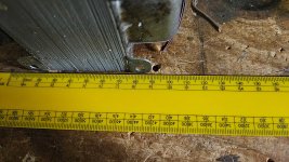
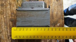
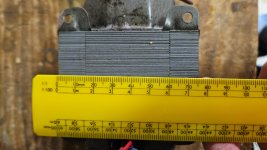
And as far as the OT goes, here is the photo. It looks a pretty decent size for a 12 W transformer, although I know relying on this is not an indicator.
Im in the same camp as you grovergardner, no engineer here and much of that maths is way over my head.
I will do as you say and see how it looks on the scope and work from there.
I guess the question is should I go with a design that uses GNFB at all? Seems that the consensus is that if done correctly , it reduces distortion, but if applied wrong, it can make it worse than without?
Ive really only messed around with this in guitar amps, particularly my marshall clone that has a presence control. With hi-fi it's a different kettle of fish, with guitar amps what's not favorable for hi-gi cam make a guitar sound awesome.
I think i will be able to sort it.
Will be a few months by the time I finish this build but will keep you posted.
And as far as the OT goes, here is the photo. It looks a pretty decent size for a 12 W transformer, although I know relying on this is not an indicator.
Attachments
If you reduce the feedback, you increase the output impedance, decrease the damping the factor and increase distortion. You just don't have as good an amplifier as you would if you used the proper amount of feedback. Eliminating the feedback altogether would result in an amp with way too much gain, a high noise floor, high distortion, reduced bandwidth and poor speaker control. Basically it would sound terrible. ;-)
You can certainly build amps without negative feedback--just not this one. ;-)
You can certainly build amps without negative feedback--just not this one. ;-)
Last edited:
It's actually not that hard to stabilize a feedback amp if you have a scope and get a little practice. "Pretty stable" is usually stable enough. 🙂 You can get used Ohmite Ohm-rangers and Cap-rangers on eBay (they're rated for 250 volts) to play around with the low-pass filter and feedback/cap combination. Or you can build a pot and variable capacitor rig. But the Ohmite decade boxes are easier to use.
Ok, I may as well stick with this design and get some experience, I have built a small ECL82 amp without NFB and it sounds OK, but you get distortion when you turn it up a bit. I found some tweaks to the design that are supposed to improve things.If you reduce the feedback, you increase the output impedance, decrease the damping the factor and increase distortion. You just don't have as good an amplifier as you would if you used the proper amount of feedback. Eliminating the feedback altogether would result in an amp with way too much gain, a high noise floor, high distortion, reduced bandwidth and poor speaker control. Basically it would sound terrible. ;-)
You can certainly build amps without negative feedback--just not this one. ;-)
I might have to wire this up a bit different however as the transformer only let's me use 16 ohms or 4 ohms, it has two secondary windings, place in parallel for 4 ohms or series for 16 ohms.
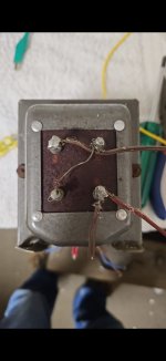
Would It might mess with the negative feedback much if i change between 16 and 4 ohms? I'm expecting i would have to modify the feedback network if I was running on 16 and decide to change to 4 ohms by wiring the secondaries in parallel instead or vice versa.
- Home
- Amplifiers
- Tubes / Valves
- Thoughts on this schematic/design?