I would appraciate any thoughts on this low power 5V regulator.
I can cram it in 5 cm2, so it can be placed very close to the point where it's needed.
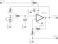
A current feedback opamp like AD811 can supply up to about 100mA, datasheet mentions voltage noise is quite low.
I measured current draw of 59mA, when feeding 10V and outputting 5V into 100 ohms.
BTW, there can't be an output capacitor !
Regards, Rudolf.
I can cram it in 5 cm2, so it can be placed very close to the point where it's needed.
A current feedback opamp like AD811 can supply up to about 100mA, datasheet mentions voltage noise is quite low.
I measured current draw of 59mA, when feeding 10V and outputting 5V into 100 ohms.
BTW, there can't be an output capacitor !
Regards, Rudolf.
Attachments
Low power supply
rbroer,
I don't see any reason why it wouldn't work, except maybe the start-up. Did you in fact check that it does start reliably? And why can there be no cap?
Cheers, Jan Didden
rbroer,
I don't see any reason why it wouldn't work, except maybe the start-up. Did you in fact check that it does start reliably? And why can there be no cap?
Cheers, Jan Didden
Good devices.
That is alright.
You TL431, one of my favourites, low noise referens.
Op amp is not that important
as long it can handle currents.
Referens is feed by the regulated votage.
Good !
As long as you can get it to start up.
In such design, sometimes Circuit will not
start up.
That is because if referens is zero,
the output of OPamp wil be
zero, and the referns can not
get any current to rise up to 2,5V.
Otherwise very good design!
gromanswe
Re: Low power supply
It works, I tested it last night. I had some concerns about starting up, but I guess since the output won't go to negative rail (=gnda), but only as low as about 2V, startup shouldn't be a problem.
No output cap, current feedback opamp don't like driving capacitive loads.
I'm just curious if it is worth making tiny pcb's;
so, will it better the average LT1085 or TL431 in respects of noise, frequency response, dynamic behaviour ?
Regards, Rudolf.
janneman
It works, I tested it last night. I had some concerns about starting up, but I guess since the output won't go to negative rail (=gnda), but only as low as about 2V, startup shouldn't be a problem.
No output cap, current feedback opamp don't like driving capacitive loads.
I'm just curious if it is worth making tiny pcb's;
so, will it better the average LT1085 or TL431 in respects of noise, frequency response, dynamic behaviour ?
Regards, Rudolf.
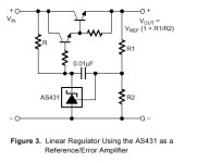
My way of Voltage regulation.
I use a combination of a temp-stabil,
zener-shunt diode and some
Current Amplifying Transistors.
See picture at bottom.
Voltage References:
TS431 (TO-92) 1.24-6.00V 0.06-30mA, low current, min 60uA
TL431 (TO-92,DIL8,SO8) 2.5-36V 1-100mA, minimum 0.500mA
both 50ppm/C temp.
TL1431 (SO8) 2.5-36V 1-100mA 13ppm/C temp, precision.
A LINK to ST products, Referenses.....PDF download
http://www.st.com/stonline/books/
-----------------------------------------------------------
This is an interesting Circuit, used to reduce noise
from regulators with about 20dB (only 1/10 of noise remains)
http://www.wenzel.com/documents/finesse.html
------------------------------------------------------------
See Picture!
You really do not need an OP.
You can use 1 or 2 transistors, depending on
how much Current is drawn.
See to that TL431 gets enough current, 1 mA recommended.
Could manage on .5mA.
TS431 only needs 60uA.
gromanswe
More about TL431, 3-pin IC
Here is download of TL431 PDF.
http://rv6llh.rsuh.ru/PDF/TL431.pdf
Of the internal diagram, we can see that this is no diode.
It is a Circuit consisting of 11 transistors.
It has some of these arranged as a bandgap referens.
It is those down at left.
This compensates for tempchanges.
It also uses some small capacitances, to avoid oscillation,
and make it stable.
In PDF is also 13 different applications.
Circuits where TL431 is used in different ways.
gromanswe
low power reg etc
Rudolf,
Yes, your asalysis of the start-up sounds correct. Re: output cap: I know a CFO are sensitive to cap loading (who isn't, these days...), but it is another matter with a cap of say 1uF or more. That should not make the circuit unstable. I think it is worthwhile to try it, it will compensate somewhat for the rising Zout with frequency.
Gromanswe,
I agree, a nifty circuit! But it is no match for Rudolfs' circuit. For one thing, your circuit has limited loop gain so inevitably the Zout will be larger leading to much larger output voltage variations with load variations. Also, the rejection of input noise & ripple will be worse. And Rudolfs' circuit can also sink current, which can be an advantage in some applications (high frequency inductive loads as in DACs).
But of course your circuit can source much higher current.
Cheers, Jan Didden
<b>ALW</b> posted this some time ago
"<i><font color=#800040>DIY Hi-Fi myths debunked - no 431.
Here's the noise spectra of a TL431, vs an LM317 and 2 samples of LT1086's.
All are set to the same o/p voltage and properly decoupled.
I'll let you guess which is which </font>🙂</i> "
<a href="http://www.diyaudio.com/forums/showthread.php?threadid=985&perpage=15&highlight=tl431s&pagenumber=2"><img src="http://www.diyaudio.com/forums/attachment.php?postid=17984" alt=""></a>
The pictures a link to the thread
James
Just a thought....
If some one wanted more current, (and maybe lower noise?) couldn't they piggy-back 2 or more amplifiers? Heat disapation might become a problem.
This would not increase the footprint but would increase the verticle dimension only a small amount.
Aud_Mot
If some one wanted more current, (and maybe lower noise?) couldn't they piggy-back 2 or more amplifiers? Heat disapation might become a problem.
This would not increase the footprint but would increase the verticle dimension only a small amount.
Aud_Mot
Substitute 78xx 79xx with YOUR fine Regulator
rbroer
You ask if you should make PCB with your circuit.
Why not make it possible to fit in 78xx and 79xx positions.
make a 20-25x60 mm PCB with 3 pins at one short end.
Then you could substitute any of those ICs
with your regulator.
I have seen such small PCBs
used for Dual OPamp -substitute, using 2 Hi Quality single OPamps.
A sort of of "piggy-back" construction.
If you need more Current you could also use an TO126 Transistor
as an output-buffer, and include it in feedback-loop.
That would take some of the pressure off the OP.
Glad for your sake, that janneman liked your design.
He is surely right is his judgement!
gromanswe
Regulators
Hi James.
I don't like guessing- I never play in the lottery- but my best guess is:
purple= TL431
red= LM317
blue/light blue= LT1086😉
Apart from the noise issue one should consider carefull the application of the regulator whether it be digital audio, analog audio; line or MC phono or a clock supply.
Rudolf came with the large cap mod 6800µF on the KWAK-CLOCK supply. Though very sceptical about this I tried it and it improved the sound! With such a large cap one should be carefull for the large inrush current and check if your rugulator can take it. Actually I am using 10000µF. A TL431 with a BC550C transistor wouldn't live long this way, I believe. LT1086 or LM317 can take it. How the AD811 reacts to the clock and the large cap I don't know for sure. I tried once a LT1021-5 and a OP27 or AD817 opamp in the scheme like proposed by Rudolf and was not impressed by the result sonically.
I am still not convinced that low noise supply= low jitter/ low phase noise😉
Up till now I've been using TL431's used as local regulators for DACs like TDA1541, Kwak Clock etc. Local bypassing with electrolyte and 805 smd duet of 10nF and 100nF of different ceramics.
I like the idea of decoupling the various supplies by the inherent use of series impedances, be it resistors or current sources.
They are easy to implement as well and have inherent current limiting. The decoupling also limits the "fighting each other" (potential) problem, which will occur with multiple regulators being fed from the same raw supply or pre-regulated supply.
Maybe they're too noisy for a high gain preamp, but so far I've not heard audible noise problems.
What I don't like about them is you need to know the maximum current draw for the circuit one is powering, this means measuring all the time since datasheets are not always correct (for example the max current draw for TDA1543).
I am hoping to get some feedback from people having tried various regulators for divers applications.
For the circuit posted and tested I have some initial doubts about PSRR at higher frequencies etc.
I like to keep things cheap and simple, so try to avoid esoteric parts, but spend space and money on (simple) individual regulators with very local bypassing, ground planes etc.
So will such an opamp approach give better sonics than using a TL431 shunt regulator when connected to the Analog power supply of a dac chip ?
And for ALW, a TL431 used as a filtered reference shouldn't be a problem ?
Rudolf.
Low power reg etc
Hi Rudolf,
How's the new government coming along in the Netherlands??
Seriously now: I have trouble following your logic on the supply architecture. Why would they 'fight each other'? They run from a common raw supply, and there may well be some load-variation-caused-noise reflected from an output to the (common) input, but that will (hopefully) be blocked by the input rejection of the other regulators.
I would never use series impedance decoupling. I know Philips used it a lot in earlier CD players, which sounded awfull (well, OK could have been coincidence). Think about it: you go to all this trouble to design a supply with zero output impedance and therefore zero variation with load variation, very low noise etc, then ruin it by a series impedance. That will surely give you load dependent supply variations where you don't want them. Or am I missing something?
Cheers, Jan Didden
As per the nice colored graphs of noise response vs. frequency response, the graph for the 431 is not valid for the whole frequency range on this forum thread. In the circuit that was suggested, the 431 output goes through an RC circuit which will limit the frequency range of the noise response of the 431. However, the noise of those resistors and capacitors can absolutely be an issue. Input current noise in the op-amp will result in a voltage noise when it flows back into the RC.
I would look very carefully at the noise spectra of the whole circuit and specifically look very carefully at the noise contribution of the RC filter between the reference and the op-amp. You may find that better filtering in front of the reference with no RC between the reference and the op-amp results in an overall lower noise circuit. When you do this, you may also want to consider some of the better references that are now on the market that have far superior noise and power supply rejection characteristics w.r.t. the 431. Unless you are planning on commercializing this, the small added cost of a better reference is warranted.
What do you plan to drive with this op-amp? If it is digital, it is virtually a given that you will have capacitive load as you will need decoupling capacitors close to the digital circuity no matter how good your regulator. You may find that a resistor at the output of the op-amp but inside the feedback loop gives you better overall performance. Not having the resistor there may result in faster overall settling, but you will likely have ringing which is probably worse than giving up some bandwidth.
Alvaius
W.R.T. does low noise = low jitter\phase noise, I can state, unequivocally, from years of analog\digital experience in communications systems, video, audio, etc. that absolutely it does, with conditions.
The condition is, what is that bandwidth of that noise and what types of circuits am I exposing it to?
I could take a 1V pk-pk sine wave at 60Hz, ride that on top of a 5V digital supply, and contribute absolutely no audibly perceptable jitter to many simple digital circuits, i.e gates, buffers, etc. Heck, it may make no difference at 1 MHz. This is all assuming good high frequency decoupling of course. If that sine wave was at 100MHz then that is a whole different story. The transitions for many logic family are so fast and the edge speeds are so fast, that low frequency power supply variatians do not cause huge jitter issues. Now if I did the same thing to a PLL, which is an analog circuit, then that 60Hz wave could do a lot, the 1 MHz would drive it crazy, and the 100MHz may go unnoticed as it would be completely filtered out [implementation dependant]. And the existence of a PLL is not always obvious. Some DACs multiply the frequency internally.
All circuits are analog at some level. Digital circuits, by their nature, often have inherent filtering of low frequencies. Analog circuits often have inherent filtering of high frequencies. When in doubt, assume nothing and experiment, but only after thinking out absolutely all the causes and effects of your circuit.
I designed a very large system imaging system many years ago. The largest contributor of noise in the A\D conversion was jitter of the sampling clock caused by noise injection through the power supply into the digital timing circuitry. That noise injection was caused by switch mode power supplies sitting in another rack 20 feet away. In theory both systems were fully isolated from each other. It is not hard to see why $300 power cords can improve your audio. However, I find that $3.00 of 8 guage battery cable ran between the chassis of your equipment and $5.00 shielded power cords works just as well... but that is for another forum which I think I will start.....
Low power etc
Alvaius,
I agree 100& with what you write. This is a very comprehensive account showing clearly that you cannot whip together an application-sheet circuit and expect it to be optimal for your particular requirement. Power supplies really are systems that need to be considered as systems regarding noise, bandwidth, Zout etc. In fact, reading your account I cannot escape the conclusion that a high performance power supply is not that different from a high performanbce power amplifier in term of issues and aspects!
I own a couple of 1970's Sony power amps, some of which have switching power supplies, some are class D switching throughout. This was quite revolutionary at the time, engineered like HF equipment. Interestingly, many people who have heard them commented on the excellent sound they produce, until I show them pictures of the output waveforms with all the switching noise and spikes...! One of the amps has a broken supply, which I am going to replace with commercially available switching supply modules. They will undoubtedly measure better, but it will be interesting to see if the perceived sound quality changes.
Cheers, Jan Didden
What Janneman states is exactly how I feel about it right now.
There are most probably different requirements for power supplies depending on what you're powering.
Up till now I've been using individual TL431's setup as shunt regulators for powering low power devices. They are fed from raw supplies.
For example a DAC&IV stage I use has individual TL431's for DAC analog supply, digital supply, the pos&neg rail of I/V & output stage and the clock circuit.
Now I do like the results, but I may be able to improve sound and here's where I need the experts on this forum.
So I would appriciate suggestions, or have people telling me I'm completely on the wrong track...
A "gut feeling" tells me the analog supplies for DAC and I/V stage might benefit from lower noise supply, clock might be fed from better supply as well, digital should be ok with these TL431's.
Life is too short to try all power supply permutations myself; this board is a great place for sharing experiences and knowledge and I've found a lot of useful info already.
alvaius,
can you tell us which references are better than a TL431 ? I've seen the LM329 but that's not 2.5V
After some searching I found the datasheet for TLV431 shows a input noise vs freq diagram. TLV431 has ca. 210nV/SqrtHz between 100Hz and 100kHz, whereas the LM329 has ca. 75nV/SqrtHz zener noise.
Regards Rudolf.
Hello rudolf.
If I should chose a device,
where the budget is not so important,
my favourite is this one.
It has Noise 1.5 uV p-p at 2.5V
temp koef 2.5ppm/C where TL431 has 50.0
can be supplied 8-36 Volts
Can drive/SINK 15 mA
Have pins for NR=noisereduction cap
and TRIM referensvoltage
Is also availeble in 4.096 V and 5.00 V
SO8 or DIL8
http://pdfserv.maxim-ic.com/arpdf/MAX6225-MAX6250.pdf
That must be a darn good referens!
Groman
good sometimes. sometimes not
- Status
- Not open for further replies.
- Home
- Amplifiers
- Solid State
- Thoughts on this low power regulator ?