Folks
For now I have parked my scratch build project as it really seems the bits I have are not going to play nice together. In the mean time I bought a Sepparo SE88I single ended KT88 amp that had been "improved" by the previous owner. It was not a happy amp when it arrived it took a while to get working as it had taken a bash in the post. The improvements consisted of removing the feedback connections, an attempt to make it triode mode by cutting off the connection from the transformer and linking the plate to the ultralinear tap via a 100 ohm resistor. The coupling caps had also been replaced with some indeterminate value Russian PIO for the first stage and output and a posh looking silver in oil between first stage and driver. when I got it running it was loud and harsh. I replaced the feedback link and that made it quieter but more obviously distorted in the vocal range particularly. So I decided to go back to the original scheme and replaced the Russian caps with some commercial grade polyester and put the silver in oil between drivers and KT88. Now it sounds OK if unexciting and a little lacking in fine detail. My thoughts are to see if I can turn this into a test bed amp. I could provide switched alternative values for the feedback, switch between ultralinear and triode and possibly (with some help!) a switched bias so I could swap the power valves for EL34 which I have a few of. Apart from that I am open to suggestions as to what could be usefully changed in the original schematic that might make interesting changes to the sound characteristics.
Thanks
AVO111
Attachments
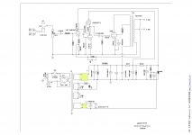
If that is the circuit, I am not impressed. Surely the drive to the output stage should be from the anode of the driver, not from the other end of the bias resistor? Why is the cathode resistor such a high value? Is it biased as class B? A 2Watt resistor in the grid to ground of the driver valve ... is there that much grid current to lose? Looks like a first year apprentice designed it.
The output valve should be biased, in single ended, at 70% of load. Possibly a 220R resistor in the cathode would be useful.
The output valve should be biased, in single ended, at 70% of load. Possibly a 220R resistor in the cathode would be useful.
Hi Jon
Thanks for the helpful comments. Should I replace the 470 ohm resistor or just parallel another resistor to get to 220 ohm ? Is the cap value still OK or does that need changing too? How about the coupling between drive and output. Should I move that to the anode of that side of the driver valve?
Is the capacitor on the input to the first stage necessary? Is the value of 0.022uF OK to make sure I don't lose any Frequency response in the audio range?
Thanks for the help with this
AVO111
It appears to be an SRPP.JonSnell Electronic said:Surely the drive to the output stage should be from the anode of the driver, not from the other end of the bias resistor?
Should I move that to the anode of that side of the driver valve?.......It appears to be an SRPP.
It is a standard SRPP circuit and is correct as shown. Moving the resistor will nullify the "advantages" of the circuit. The SRPP was in vogue among the "audio illuminati" about 10 years ago. It has fallen out of favor now that better designs exist, but it can still deliver respectable performance. An SRPP with a 12AU7......wouldn't be my favorite choice, but I have never tried it.
The SRPP is a compound circuit. The bottom tube is a typical common cathode voltage amp, while the top tube bootstraps the plate load to improve distortion and gain. The top tube also acts as a cathode follower to buffer the load. For the circuit to work "right" the cathode resistors for each tube should be the same value. "Experts" disagree on whether the bottom resistor should be bypassed. It is usually not bypassed.....as in this design.
A 2Watt resistor in the grid to ground of the driver valve ... is there that much grid current to lose?
Yep, no electrical reason for that....but maybe the original designer had a large pile of them, or maybe that's the only non inductive resistor he could get.
560K for the grid resistor is way over spec for a KT88. The original Genalex spec calls for 220K in cathode bias. Modern new production usually benefits from an even lower value to prevent runaway, but this sacrifices gain, so it is commonly ignored. Tube runaway near end of tube life is the common result.
Possibly a 220R resistor in the cathode would be useful. Should I replace the 470 ohm resistor or just parallel another resistor to get to 220 ohm ?
There is no way to know what size cathode resistor to use in this circuit without knowing the B+ voltage. It would also be prudent to measure the voltage across the existing resistor to determine the current before blindly swapping parts.
The SSE runs a 560 ohm resistor and that puts the KT88 near the upper limit on a 430 volt supply. I have a 470 ohm resistor in mine and I am running 100mA on 430 volts. That puts the dissipation in the KT88 at 38 watts. A 220 ohm would melt the tube in an amp with 430 volts of B+, but may be OK if the B+ was really low.
Raising the current through the tube could increase distortion due to saturation, or even damage the OPT if it is undersized. I don't know this amp, but many Chinese designs skimp on the OPT.
Is the capacitor on the input to the first stage necessary? Is the value of 0.022uF OK
The cap is not necessary, but may help reduce noise with cheap pots and input tubes that draw some grid current due to internal gas. It can probably be eliminated here.
Quote:
Is the capacitor on the input to the first stage necessary? Is the value of 0.022uF OK
Yes, it will protect the input stage from DC from the source, and it won't affect the sound as it is. The value is ok.
Is the capacitor on the input to the first stage necessary? Is the value of 0.022uF OK
Yes, it will protect the input stage from DC from the source, and it won't affect the sound as it is. The value is ok.
Thanks for the replies folks. Here are some values from the amp.
B+ to output transformer 388V
supply to 12AU7 204V
supply to12AX7 204V
drop across 470R cathode bias resistor for KT88 34.5V current =73ma =26W
If I have that right I should be able to reduce the 470R
Am I right🙂
Thanks
AVO111
B+ to output transformer 388V
supply to 12AU7 204V
supply to12AX7 204V
drop across 470R cathode bias resistor for KT88 34.5V current =73ma =26W
If I have that right I should be able to reduce the 470R
Am I right🙂
Thanks
AVO111
If I have that right I should be able to reduce the 470R
Yes. Depending on the KT88 you can go up to 32 watts, maybe higher. I have Electro Harmonix KT88's in my amp. They are about 6 years old and have been running at 38 watts for most of that time.
Increasing the current will not usually result in a significant power increase, but will boost the damping factor and possibly lower the distortion. The added damping factor can improve the bass quality on some speakers.
You can increase the current by adding a resistor in parallel with the 470 ohm that is already there. I put some alligator clips on the wires of some 1.5K and 2.2K 2 watt resistors. I just clip one or both across the 470 ohm when I want the increased current.
Folks
I have got some more bits and started modding this thing. The first step has been to parallel a 1.5K across the 470 R on the KT88. This drops the resistance to around 370 R. Soundwise it seems to have reduced the bass rather than improve it, Currently I am driving into some Quad ESL63 and there is much less bottom end than either my Audiolab 8000 or my EL 34 single ended however that is more bass shy with these speakers than the CELEF 3ways I was previously using. What should I look at next? Really I would like to get a bit more bass and possibly more clarity at the top end, again the EL34 amp is doing a better job despite having much smaller OPTs and being wired pentode rather than ultralinear like the sepparo amp!
Thanks for you help with this
The perception of less bass can be a consequence of lower distortion.Avo111 said:Soundwise it seems to have reduced the bass rather than improve it
Shef, I don't understand your comment the feedback is there are you suggesting I increase resistance or do something else?
For the 3-stage the 120K seems excessive, lots of schematics have it 0.5K-20K. If you remove it and just listen you may notice no difference... i.e. then why not join those of us who avoid the GNFB )) completely?
Otherwise, the deeper NFB might be a great help to cope with difficult load: to significantly lower the amp's output impedance (as I had to do for my B&W speakers', non-linear quite a bit).
IMO of course.
Otherwise, the deeper NFB might be a great help to cope with difficult load: to significantly lower the amp's output impedance (as I had to do for my B&W speakers', non-linear quite a bit).
IMO of course.
Shef, I am misunderstanding something. Surely replacing the 120K with a 20K will increase rather than reduce the NFB as it will pass more current? When I got the amp it had the NFB disconnected and it sounded very harsh if somewhat louder. So should I increase resistance to reduce NFB or reduce it to increase NFB? which will likely improve Bass?
Thanks!
Thanks!
Reducing the GNFB resistor will certainly make the amp quieter (unless the FB is positive, by mistake), and _maybe_ soften the harshness. You can try 20K and see if you like it better. Even the value of 1K is not very unusual, saw it 300 E.
But instead, you may lower the gain. Do what is best to your ear.
About the bass... several conditions should be considered, e.g. the mentioned speaker's impedance. Increasing the NFB most likely will make the amp better handling the speakers with lower impedance. Another is how good (or, how appropriate) the crossover filter is. I.e. some speakers might work with your amp just fine, but some... not.
There is no quick answer.
Yep, by increasing the current you have increased the damping factor which generally will create tighter bass - but human perception will interpret that as weaker bass.The perception of less bass can be a consequence of lower distortion.
Shoog
Minor change in damping factor is a separate issue from distortion, but that too can give a perception of less bass.
OK we are seemingly only finding things that potentially reduce bass. What can I do to add or enhance bass? Are there any of the signal capacitors that could be changed to improve things?
thanks
thanks
Do you want more bass or better bass (i.e. closer to the source)? To get more bass try one of the following:
1. add tone controls before the amp
2. reduce negative feedback thus raising output impedance - you can get it as boomy as the speakers will allow
3. increase distortion, this giving the perception of more bass
4. buy a better (i.e. more expensive) OPT
It is only an SE amp, so don't expect miracles.
- Status
- Not open for further replies.
- Home
- Amplifiers
- Tubes / Valves
- Thoughts on amp mods