Re: having cake and eating it too
I believe the people who suggested this didn't try it out in a real environment. Instead of speculating, build it, connect low capacitance, then big capacitance and let your ears decide. It is that simple. 😉
I used to built stuff by choosing parts according to my likening. I used to think: this part looks good, so it must sound good too. I never bothered to to listen. Recently I started to listen when choosing parts. And it makes all the differnce. 😉
I checked my original PS yesterday and MUR860 from Motorola seems to be even better than MUR1520 from IR. And adding 4.7 BG N beside the bridge definitely improves highs (less harsh). Placing 1000u BG right after bridge degrades sound. 1000U BG on ea. rail per chip is definitely enough in certain gainclone arrangements.
David B said:Some have suggested here that relatively high capacitance in the powersupply is good for bass and not so good for mid/high, and vice versa for low capacitance.
I believe the people who suggested this didn't try it out in a real environment. Instead of speculating, build it, connect low capacitance, then big capacitance and let your ears decide. It is that simple. 😉
I used to built stuff by choosing parts according to my likening. I used to think: this part looks good, so it must sound good too. I never bothered to to listen. Recently I started to listen when choosing parts. And it makes all the differnce. 😉
I checked my original PS yesterday and MUR860 from Motorola seems to be even better than MUR1520 from IR. And adding 4.7 BG N beside the bridge definitely improves highs (less harsh). Placing 1000u BG right after bridge degrades sound. 1000U BG on ea. rail per chip is definitely enough in certain gainclone arrangements.
Re: Peter Daniel Gain Clone Schematic
My PS wiring is different. I run ea. secondary to a separate bridge. Secondaries and bridges are not connected inside the PS. I also run separate grounds for + and - rails and they connect only at amps star ground. According to your schematic there is no reason to run separate ground wire for + and - rail, because they are common (connected at PS).
Algar_emi said:Here a complete schematic schematic of Peter Daniel Gain Clone Version in PDF format including the power supply. Let me know if you have any comment.
My PS wiring is different. I run ea. secondary to a separate bridge. Secondaries and bridges are not connected inside the PS. I also run separate grounds for + and - rails and they connect only at amps star ground. According to your schematic there is no reason to run separate ground wire for + and - rail, because they are common (connected at PS).
Re: Peter Daniel Gain Clone BOM
You have $45USD for Cardas speaker cable. What is it for?😉
Algar_emi said:Here the parts list with prices and distributors.
You have $45USD for Cardas speaker cable. What is it for?😉
Cardas Wire
I was expecting to use short lenght pf Cardas Crosslink speaker cable for the Power cable between the power supply and the Amp. This is the only OFC copper cable that I can easily get. Price is around 8$ per feet.
I was expecting to use short lenght pf Cardas Crosslink speaker cable for the Power cable between the power supply and the Amp. This is the only OFC copper cable that I can easily get. Price is around 8$ per feet.
Re: Cardas Wire
FYI, wirewrap wire is OFC and is readily available.
Oh, and considerably less than $8 a foot. 🙂
se
Algar_emi said:I was expecting to use short lenght pf Cardas Crosslink speaker cable for the Power cable between the power supply and the Amp. This is the only OFC copper cable that I can easily get. Price is around 8$ per feet.
FYI, wirewrap wire is OFC and is readily available.
Oh, and considerably less than $8 a foot. 🙂
se
$8 a foot is definitely too expensive and probably not practical as well. I'm using Kimber 4TC which has exactly 8 wires, some of my friends actually prefer regular silver plated copper hook up wire (teflon) to Kimber as having more body and better tonal balance. Also Cat 5 cable might be a good alternative.
Peter Daniel Gain Clone Schematic Corrected
Hi Peter. Thanks for the precision on the power supply. One reason I did this schematic was to compiled all the comments on your Desing in this post. Check this version and tell me if I got your explanations correctly. Let me know if there is any other changes to do.
Hi Peter. Thanks for the precision on the power supply. One reason I did this schematic was to compiled all the comments on your Desing in this post. Check this version and tell me if I got your explanations correctly. Let me know if there is any other changes to do.
Attachments
Power Supply Wire
Thanks for your comment on the Wire. Peter, do you know a distributor of Kimber 4TC and also the price so I can update the parts list.
Thanks for your comment on the Wire. Peter, do you know a distributor of Kimber 4TC and also the price so I can update the parts list.
It looks good now. I also found that placing 4.7BG N caps in PS after ea bridge (total 2) improves things. As I mentioned earlier MUR860 might be even a better choice.
Gain Clone latest update
Hi Peter. I will wait for the cable answer from you, then I will send both updated schematic and part list.
Hi Peter. I will wait for the cable answer from you, then I will send both updated schematic and part list.
Bypassing
Unless I have missed it somewhere, I haven't seen any suggestions for bypassing the 1000 u's with something smaller (or any of the caps for that matter).
With a smaller bypass cap, it may be possible to increase the overall capacitance without the trade-off that Peter has experienced.
Any comments? I appreciate that part of the fun with the Gainclone is keeping the parts to a bare minimum but if a small cap can improve the sound....
And while I'm here can somebody tell me if I have to have four wires on the secondary side of my transformers to use two separate bridges. Mine have just three wires.
Bypassing 1000u with 4.7u doesn't seem like increasing total capacitance by much as the intention here is to attenuate diodes switching noise (as suggested by Fred)😉. N type BG also improve the sonic character of the 1000u caps which are standard grade.
Peter Daniel said:Also Cat 5 cable might be a good alternative.
do you mean using one wire for each connection? does it have a high enough current rating? if it does, good, because i have about 8 meters of it (i think) (the solid core wire type).
[edit]: isnt solid core wire the best conductor you can have? if so, why dont people use bell wire or similar? unless your experimenting alot, your ampa dn speakers dont need to move around alot, so solid core wire should be fine, right?
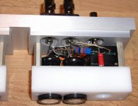
Peter Daniel said:That's my latest implementation of gainclone circuit. Now my amp has not only 3/4" aluminum front but back panel also. Who else?😎 😉
Great! My Alcoa stock just went up 10 points! Thanks, Peter! 🙂
se
No problem. I don't know if it's because of thickness, but it seems to be sounding substantially better than previous version which had only 1/2" panels..😉
- Status
- Not open for further replies.
- Home
- Amplifiers
- Chip Amps
- This is not just another gainclone