mac said:
well, thats exactly what i have...
Jan-Peter said:You must ground the amp only at one side! Never use star grounding, which fool that has designed.....
JP
well, there are a lot of fools on this forum then... star grounding is a common practice from what i thought. but if there is a different and better way to do it for your amp, ill learn. its obviously not working for me now.
OK, so lets get this straight... i have a power supply, that looks just like the picture mac posted. i have 3 connections coming out of it. do i connect THAT ground to the UCD module? or JUST the RCA tab ground?
edit:
i just followed the directions on the supplied manual diagram, and only added a star ground AFTER i got humming.
There is no need to ground at the center of the capacitors. Please ground only at the input of your RCA connector.
You can very easy test it in your setup, remove the star ground. Connect a wire from the RCA GND tab to the chassis. And connect -sym at the UcD180 module to GND.
Connect the center of you capacitors ONLY to the GND of the UcD180. Remove also here the star ground.
JP
You can very easy test it in your setup, remove the star ground. Connect a wire from the RCA GND tab to the chassis. And connect -sym at the UcD180 module to GND.
Connect the center of you capacitors ONLY to the GND of the UcD180. Remove also here the star ground.
JP
Jan-Peter said:There is no need to ground at the center of the capacitors. Please ground only at the input of your RCA connector.
You can very easy test it in your setup, remove the star ground. Connect a wire from the RCA GND tab to the chassis. And connect -sym at the UcD180 module to GND.
Connect the center of you capacitors ONLY to the GND of the UcD180. Remove also here the star ground.
JP
yes, i tried that... and the module didnt turn on. i dont have a star ground anymore. the only way it turns on is when i have a wire connected from the center of the cap bank to J5 on the UCD board.
the only other ground connections i have are: from the speaker terminals to the UCD board (necessary), and from the RCA ground tab to the UCD board (-sym, and input ground).
thats the ONLY grounding thats going on.
Watch our website, unther Applications. We will put today some drawings how to proper wiring the UcD module in a met case.
Jan-Peter
Jan-Peter
Jan-Peter said:Watch our website, unther Applications. We will put today some drawings how to proper wiring the UcD module in a met case.
Jan-Peter
ok. its late here and im going to get some sleep. ill mess around with it again tomorrow. it just seems strange that im having problems (not being a complete beginner, i have working amps that i built from scratch that run fine). and i see so many beginners tossing these things together in a few hours on wood boards and just hand-wired together without problems. it must be something simple. tomorrow, ill try the other UCD and see if maybe it has a problem.
It may not be "correct", but I was able to drive the module single ended with non inverting input to + RCA and inverting input to RCA ground, the module's signal ground was left to float, grounding it to inverting input produced alot of hum.
Having the modules wired out of phase in stereo produced alot more hum on one channel over the other. Wiring them in phase produced equal levels of hum (the same as on the quieter channel previously). Any attempt at grounding the signal ground to the star point produced noise/hash, which remained the same regardless of where that ground was brought.
Point is: Star grounding for the simple supply as per the data sheet works equally well for me in balanced or unbalanced provided the signal ground is left to float (with or without shield attached), which I guess then grounds it through the power GND /star point and so is obviously not ideal.
dominate
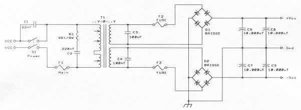
Is it just me, or do the capacitors look like they are wired kind of oddly? Is there a ground between the rectifiers?
maybe it's just hard to see in the pictures...
Is it just me, or do the capacitors look like they are wired kind of oddly? Is there a ground between the rectifiers?
maybe it's just hard to see in the pictures...
Guys, please check this link; http://www.hypex.nl/docs/wiring.pdf
Drawing: Interfacing unbalanced source / balanced amplifier
The RCA connector must be a female instead of a male.
I hope this will give enough information.
Regards,
Jan-Peter
Drawing: Interfacing unbalanced source / balanced amplifier
The RCA connector must be a female instead of a male.
I hope this will give enough information.
Regards,
Jan-Peter
classd4sure said:It may not be "correct", but I was able to drive the module single ended with non inverting input to + RCA and inverting input to RCA ground, the module's signal ground was left to float, grounding it to inverting input produced alot of hum.
Having the modules wired out of phase in stereo produced alot more hum on one channel over the other. Wiring them in phase produced equal levels of hum (the same as on the quieter channel previously). Any attempt at grounding the signal ground to the star point produced noise/hash, which remained the same regardless of where that ground was brought.
Point is: Star grounding for the simple supply as per the data sheet works equally well for me in balanced or unbalanced provided the signal ground is left to float (with or without shield attached), which I guess then grounds it through the power GND /star point and so is obviously not ideal.
hum. that all makes some sense and i will have to try it. Jan's diagram is nice and all, but thats exactly how ive been doing it. its nothing new, and its stuff ive tried. ive had enough grounding problems in my day to know what to try...
ill give yours a shot. one question though, is your amp quiet now? did you get it to work without any noise?
lne937s,
ill take a better picture of the wiring as i have it now. im not sure what you mean "ground between rectifiers". ill take a better picture and detail how its hooked up a bit better.
Jan's diagram is nice and all, but thats exactly how ive been doing it.
You have to remove the mains ground, of course only if you have a double insulation transformer! (=tested with 4KV). With an asymmetrical connection and connection to mains ground you will have groundloops......
All our amps wired in the symmetrical way and with the special symmetrical to asymmetrical cable are DEAD QUITE (even when we turn up our passive preamp to the maximum volume and the SACD player in PAUZE mode).

Jan-Peter
well, i think i figured it out.
i did what classd4sure said and floated the signal ground. it really didnt help much, so i just attached it to the chassis, and it was quiet with nothing connected. however, when i connected ANYTHING to the rca, i got a small hum. just guessing randomly, i connected the earth ground to the same point on the chassis, and now its dead quiet. so, thats good.
im going to do a bit more testing in the next few days.
i did notice one thing thats strange... i connected an 8ohm 100-watt dummy load to the speaker terminals and put a pretty good signal into the amp. i was getting around 15vac on the outputs (so just shy of 30 watts of power) into the dummy load. i heard a wierd noise. i put my ear very close to the UCD module and heard the music very very faintly coming from what i assume to be the coil... and when i looked at the light bulb (the one i have in series with the main in place of a fuse), it was glowing every so slightly. is that just the nature of having a light bulb in line with the mains? or does the amp itself create a little bit of noise?
cowanrg said:
hum. that all makes some sense and i will have to try it. Jan's diagram is nice and all, but thats exactly how ive been doing it. its nothing new, and its stuff ive tried. ive had enough grounding problems in my day to know what to try...
ill give yours a shot. one question though, is your amp quiet now? did you get it to work without any noise?
lne937s,
ill take a better picture of the wiring as i have it now. im not sure what you mean "ground between rectifiers". ill take a better picture and detail how its hooked up a bit better.
Dead quiet, always has been. I was in a quest for perfection so I tried different schemes with what I had (still not using connectors) and everything was worse. So I drove it for weeks like I told you, signal gnd left to float but it still grounds via the module and power gnd which is tied to star point/center tap/static screen/earth and is dead quiet with a 102db efficient speaker only a slight hiss is ever heard with the ear less than a foot from the tweeter. Sounds like you're doing it my way after all.
Grounding the shield/signalll gnd to chassis at any point still produced mild noise, but not hum.
So it works, but I see the key difference as my way references the input to the output, while JP's way is the preferred opposite.
Right now I'm using fully balanced so it's not a concern, but I'll be further experimenting myself, as I'm building a much better supply, more like yours. Parts should be here now in fact, see ya later🙂
Actually before I go, JP are you advocating no earth ground at all in the amp? What do you do with the static screen, leaving that disconnected gave me an ugly imbalance.
Regards,
Chris
Actually before I go, JP are you advocating no earth ground at all in the amp? What do you do with the static screen, leaving that disconnected gave me an ugly imbalance.
When you have an earth ground connection -----> use balanced input 😉
Because the UcD-modules are having a tru balanced input (instrumential input design!) you can take the advantage to use this.....
Jan-Peter
Hi,
I sense some confusion. When JP writes "don't ground at the power supply" he means: don't connect the PSU ground to the chassis. But you *should* of course have all 3 wires going from the PSU to the amplifier 🙂
Here's the full recipe for wiring up an RCA chassis part:
*Use non-insulated RCA chassis parts. They will serve as the chassis connection for the whole amp. You don't want to have the whole amp floating in the chassis or you'll get one heck of a buzz when you leave the inputs open.
*Make no other chassis connection elsewhere, but otherwise wire the whole thing normally.
*Preferably use shielded twisted-pair cable, such as microphone cable.
*Tie pin 1 of the module's input connector (J7) to the RCA signal pin using one of the two conductors.
*Tie pin 3 of J7 to the RCA ground lug using the second conductor.
*Tie pin 2 of J7 to the RCA ground lug as well using the cable shield. This step insures the amplifier is no longer floating with respect to chassis.
This method insures that any ground currents flow through the shield, not through the "cold" wire on pin 3.
If you have a substantial personal preference for using 3 separate wires instead of a shielded twisted pair, at least twist the 3 wires together.
The problem with unbalanced (RCA) connections is obviously the sensitivity to ground loops. Because of this, you should not connect the chassis to mains earth. Instead, follow double-insulated construction methods on the primary side for safety.
There are a few tricks to make an RCA input "pseudo differential" using the differential input of the UcD module, but I'm afraid to "float" them here because that will cause more confusion. Besides, the above description is the most solid because using uninsulated RCA parts also keeps your amps from RF break-in.
Having said all that, it is always best to use XLR inputs and build a "converter cable" (see new doc on Hypex site) that extends the differential sensing trick all the way to the pre outs.
We're advocating using XLR inputs.classd4sure said:Actually before I go, JP are you advocating no earth ground at all in the amp? What do you do with the static screen, leaving that disconnected gave me an ugly imbalance.
Unbalanced inputs will only work acceptably when all devices are floating (or only one is grounded). Otherwise you're bound to run into ground loop problems at some stage. This has nothing to do with this specific situation. It's the same in all unbalanced gear, except when people buy modules they have someone to ask how to solve their grounding problems 🙂
I thought having differential inputs would immediately solve anyones problem, but I forgot the human factor. One more wire is one more source of confusion.
classd4sure,
thanks again for the help, it all works great, and now i understand what is going on and why i had hum before. i didnt hear any noise at all from my speakers, but my shop isnt exactly the quietest place in the world. i only settle for absolutely silent, even a slight hiss is a bad thing. i use 6ft tall line arrays and with my ears, even the slightest hiss i can hear in the room. i ususally keep my amps on all the time too.
Bruno,
thanks, that is the explaination i was looking for from the beginning. in all the other projects ive done before, it is very different. im used to having the RCA jack completely isolated and having a star ground. so, this was just a bit new to me.
also, i was confused when jan said not to ground to the center of the caps. i was curious how the unit would work. but now i get what he was saying...
having the unit rely on balanced (XLR) inputs is nice, but there are plenty of people out there that use single-ended. i use single-ended only because most home theater gear is NOT balanced, and if it is, its VERY pricey. plus, i have pretty expensive interconnects and once i buy them once, i dont want to replace them all for balanced.
could either Jan or Bruno address my "issue" with hearing the music through the unit itself? is this just because im using a light bulb in series, or is there another issue at hand? thanks!
- Status
- Not open for further replies.
- Home
- Amplifiers
- Class D
- thinking about the UCD modules.