A few posts have addressed my segmented build, so I thought I'd comment on a few of the issues raised.
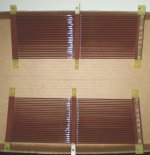
I did use the drop-ceiling lighting louvers as the basis for my panels. For one set I used the 3/8" thick louvers and felt I had to add stiffening rods to the back of the panel as it flexed more than i would have liked. For another set, I used the 1/2" thick loluvers. This was _much_ more rigid and did not require the reinforcements.
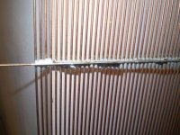
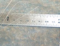
I used 0.035 TIG rod spaced at 13 per inch (using a piece of all-thread as a guide). There was no ringing problem with the rod as I ran a bead of adhesive across each cell of the louver, essentially supporting the rod every 1/2"
In post 8 Golfnut posited that ideally the more segments the better. In practice, I was not able to hear or measure any improvement once I made the segments smaller than about 1.25" (on a 15" wide panel). Perhaps others have experience to the contrary.
In post 12, onewaypockets asked if anyone had heard both the perf metal flat (or curved) stator and segmented stator versions and could comment. My first ESLs were back in 1987 and were a set of Martin Logan CLSII (still have them). Also, my first few panels were flat perf metal panels. Having heard all three, it is a toss-up to me between the curved ML CLSII and the Segmented flat panels. Both I found to be superior to the flat perf metal panels. The flat panels have a grest sound - if you are in the exact sweet spot. The curved panels and the segmented panels have a far wider sweet spot. I can actually walk around and listen to the segmented panels. This came at a lower efficiency, however. Calving did a great job in laying our the differences in post 13.
To answer the question about "hot" solvents, that is a real issue in California. I did have to settle on using several small spray cans. These worked adequately and I have been able to run at a 3.5kV bias with no issues.
I did use the drop-ceiling lighting louvers as the basis for my panels. For one set I used the 3/8" thick louvers and felt I had to add stiffening rods to the back of the panel as it flexed more than i would have liked. For another set, I used the 1/2" thick loluvers. This was _much_ more rigid and did not require the reinforcements.
I used 0.035 TIG rod spaced at 13 per inch (using a piece of all-thread as a guide). There was no ringing problem with the rod as I ran a bead of adhesive across each cell of the louver, essentially supporting the rod every 1/2"
In post 8 Golfnut posited that ideally the more segments the better. In practice, I was not able to hear or measure any improvement once I made the segments smaller than about 1.25" (on a 15" wide panel). Perhaps others have experience to the contrary.
In post 12, onewaypockets asked if anyone had heard both the perf metal flat (or curved) stator and segmented stator versions and could comment. My first ESLs were back in 1987 and were a set of Martin Logan CLSII (still have them). Also, my first few panels were flat perf metal panels. Having heard all three, it is a toss-up to me between the curved ML CLSII and the Segmented flat panels. Both I found to be superior to the flat perf metal panels. The flat panels have a grest sound - if you are in the exact sweet spot. The curved panels and the segmented panels have a far wider sweet spot. I can actually walk around and listen to the segmented panels. This came at a lower efficiency, however. Calving did a great job in laying our the differences in post 13.
To answer the question about "hot" solvents, that is a real issue in California. I did have to settle on using several small spray cans. These worked adequately and I have been able to run at a 3.5kV bias with no issues.
Hi,
I have to agree about problems with rigidity while using 3/8 thick luovers. Some quite long time ago I experimented with relatively small panels, having external dimensions about 0.12x1.0 meter. The rigidity was just good enough for these narrow elements. I have used PVC insulated wire with external diameter of ~1 mm. As it turned out panels were too small for my needs so project abandoned.
The glue was the same as pioneered by acoustat : louvre material dissolved in metylene chloride to a consistency like a syrup. Strangely enough it was possible to apply this glue via syringe with rubber padding as it did not weaken fast. So, if you have access to well ventilated area and metylene chloride it might be an option. Note that contact with skin & inhaling vapour of metylene chloride should be avoided.
Later I decided to give up ceiling material for self-built ladder-like structure because of rigidity & difficulty of gluing wires.
Cheers
Lukas.
Last edited:
In post 8 Golfnut posited that ideally the more segments the better. In practice, I was not able to hear or measure any improvement once I made the segments smaller than about 1.25" (on a 15" wide panel). Perhaps others have experience to the contrary.
How small you can make the segments before there is no further dispersion improvement, depends on the fL(low frequency bandwidth limit) you choose. For a given panel width and fL, once you have increased the number of segments(ie reduced segment size) to the point that fH(upper bandwidth limit) is > 100kHz, you will not measure/hear much if any improvement in dispersion below 20kHz.
The rule of thumb I use for a given fL, is that there is little advantage to use more segments than:
N = sqrt[ 100000 / (4*fL) ]
With fL and number of segments determined, dispersion is improved by reducing the total panel width(and thus segment width as well). The down-side is that SPL is reduced. Alternatively, you could reduce fL which would increase N and improve dispersion. But again, SPL is reduced. This is the compromise that needs to be juggled between SPL, dispersion, size, and low frequency extension(ie fL). The consequence is that in general, full range segmented ESLs(fL<100Hz) are capable of better dispersion performance than hybrid segmented ESLs(fL>200Hz), but that comes at the cost of lower SPL.
This interdependence of dispersion and SPL were discussed in Golfnut's AES paper at the end of Section 2.
“…there is a direct compromise between the angular extent of the high-frequency polar response, which broadens with increasing intersegment coupling resistance, and the SPL, which decreases with increasing resistance.”
Last edited:
SyBorg.....
"The flat panels have a grest sound - if you are in the exact sweet spot. The curved panels and the segmented panels have a far wider sweet spot. I can actually walk around and listen to the segmented panels. {This came at a lower efficiency}"
Yes the ML panels can be fun...An add a 10 driver to each panel...thay well play loud....but after you hear the full rang ESL...most are spoiled...
an then IT all about the efficiency...of the flat,curved, segmented,Verticel, horizal, panels, Amps, Bias, Tranfourmers room humidity........an in the end...it Just dose not work for me!..An as I get older an am like most loseing some hearing
i well play my sound at lower SPL...I think not.....
bute I had to go to know...
If I new what I know now 30years a go...hehe.....right...
I would have just keep the Quad 57
for a tonel ref....an move on to ribbons....
thanks to all.... for all the info.....
Last edited:
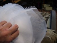
Yes, I had similar issues with the Egg Crate material when I made my 8.5" wide panels.
Bowing across the width while the diaphragm is under tension was the main issues even though they still worked.
Whether you cut out some square sections to open up the area and just leave some horizontal strip sections for support or leave it as a whole it still bends easily.
I have found that using the technique known as "Boxing it in" greatly increases its rigidity.
This accomplished by simply gluing on some plastic strips to the material.
Even on my little panels that I had used this method they seemed to be more rigid along its vertical longest length of 10" than they did among its shorted 4" width as they were only boxed in around its perimeter.
I didn't think to add a few horizontal strips as it wasn't really an issue for the narrower panels, but my larger 8.5" panel certainly would have benefited from this had I added them.
I had thought about this for 7 years looking for something to fix this, and it wasn't until I had get back into this hobby and found that when the strips that I had on them had come loose, and when I re-glued them back on (this time not being stingy as to how much glue I used) that they were much more rigid than I had thought.
All I used was some thin sheet of .020" or so Drafting Acetate or Drafting Mylar of some sort that I got at a local print shop and super glue.
I still have an untouched 48" piece of this stuff that I got just for this purpose for some 1'x4' panels using window screen, but I never got around to making them.
I still have the two pieces of egg crate as well. 😉
At the time I didn't know how much (if any) the support structures would effect the overall performance.
Now I have found out that it makes little, too at least No difference, that I can hear and theoretically speaking.
Just yesterday I was examining my new build and one of the end cap pieces broke off of one end again and they offer no added support what so ever and it is still Very Strong and rigid they way it is constructed all sandwiched together.
Although this is a slight flaw that I will have to change though, as the end pieces are need to support the ends of the diaphragm.
The end sandwiching bolts do not go through those pieces and should be.
Again I used super glue to build the frames and it is not very strong, I would have used the proper Acrylic Adhesive Solvent but I don't have any at this moment.
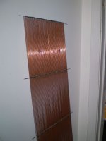
Even my 10.5"x 36" stator's are very rigid and as is need no extra support than what it has, which is just one TIG rod soldered across its span every 9".
It wont need anymore than this once it is mounted to a rigid frame.
However this one does use 1/16" rod and is why I suggest to you may be able to get away with this method using some smaller .045" rod.
I think that if you use some 1/16" rod for support depending on how wide the sections are it may work as well with .035" rods supported say every 6 inches or so, or, maybe it will be just fine with .035 rod pieces for support.
You will have to build a test design to find out as the thinner stuff wasn't available when I made mine in 2004-5.
It may be possible to use the spooled stuff if you want to go through all of the trouble building a stretching jig and heat temper them while you have tension on them.
IMHO it is not worth the extra labor since you can get the stuff at any good welding supply house in straight form now.
I selected each rod by rolling it on a flat glass surface and the supply house charged me by the pound for it.
So it was no issue to them for me to take back the slightly warped ones for another batch to select from.
Once you get them made then you can coat each section but you can forget about powder coating with this method because powder coating cures at a higher temp than the melting point of solder.
I went through Two soldering guns to make my (so far Six) screens and it was a lot of work.
I had planed on building a jig to make some more and this would make things a whole lot easier and you can easily use some big heat to quickly solder the ends and support from a torch of some sort.
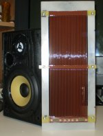
This where I had thought of using some plate material for the supports and then you could use a though hole bolt to secure each section to the frame and connections to each of the sections.
I made these on my desktop on piece of Formica coated shelving material that I had.
At the time I didn't know about segmentation or how to plan the dimension sizes.
I just wanted to make them and Perforated metal was quite expensive even then.
I do have a big time distributor in my area ALRO Steel and it would cost me nothing for shipping, but It was still a cheaper method even including my labor!!
Anyhow, although some of the warped piece may have worked I am some what of a perfectionist and I wanted them to be perfectly flat.
A few of those warped pieces did wander in to my smaller build and it just irritates me when I notice them.
You'll know it as well when you are trying to assemble the thing and the tines keep snapping out of place or are touching the ones next to it when it shouldn't be.
So save yourself some aggravation and make sure that your material is perfectly straight.
I do know that Charlie knows all about this!!!! He,he,he,he 🙂
I wish I knew how to use CAD and then I could draw it up very easily some of the methods that I have in mind for all of you to check out.
Cheers !!!
jer 🙂
Bowing across the width while the diaphragm is under tension was the main issues even though they still worked.
Whether you cut out some square sections to open up the area and just leave some horizontal strip sections for support or leave it as a whole it still bends easily.
I have found that using the technique known as "Boxing it in" greatly increases its rigidity.
This accomplished by simply gluing on some plastic strips to the material.
Even on my little panels that I had used this method they seemed to be more rigid along its vertical longest length of 10" than they did among its shorted 4" width as they were only boxed in around its perimeter.
I didn't think to add a few horizontal strips as it wasn't really an issue for the narrower panels, but my larger 8.5" panel certainly would have benefited from this had I added them.
I had thought about this for 7 years looking for something to fix this, and it wasn't until I had get back into this hobby and found that when the strips that I had on them had come loose, and when I re-glued them back on (this time not being stingy as to how much glue I used) that they were much more rigid than I had thought.
All I used was some thin sheet of .020" or so Drafting Acetate or Drafting Mylar of some sort that I got at a local print shop and super glue.
I still have an untouched 48" piece of this stuff that I got just for this purpose for some 1'x4' panels using window screen, but I never got around to making them.
I still have the two pieces of egg crate as well. 😉
At the time I didn't know how much (if any) the support structures would effect the overall performance.
Now I have found out that it makes little, too at least No difference, that I can hear and theoretically speaking.
Just yesterday I was examining my new build and one of the end cap pieces broke off of one end again and they offer no added support what so ever and it is still Very Strong and rigid they way it is constructed all sandwiched together.
Although this is a slight flaw that I will have to change though, as the end pieces are need to support the ends of the diaphragm.
The end sandwiching bolts do not go through those pieces and should be.
Again I used super glue to build the frames and it is not very strong, I would have used the proper Acrylic Adhesive Solvent but I don't have any at this moment.
Even my 10.5"x 36" stator's are very rigid and as is need no extra support than what it has, which is just one TIG rod soldered across its span every 9".
It wont need anymore than this once it is mounted to a rigid frame.
However this one does use 1/16" rod and is why I suggest to you may be able to get away with this method using some smaller .045" rod.
I think that if you use some 1/16" rod for support depending on how wide the sections are it may work as well with .035" rods supported say every 6 inches or so, or, maybe it will be just fine with .035 rod pieces for support.
You will have to build a test design to find out as the thinner stuff wasn't available when I made mine in 2004-5.
It may be possible to use the spooled stuff if you want to go through all of the trouble building a stretching jig and heat temper them while you have tension on them.
IMHO it is not worth the extra labor since you can get the stuff at any good welding supply house in straight form now.
I selected each rod by rolling it on a flat glass surface and the supply house charged me by the pound for it.
So it was no issue to them for me to take back the slightly warped ones for another batch to select from.
Once you get them made then you can coat each section but you can forget about powder coating with this method because powder coating cures at a higher temp than the melting point of solder.
I went through Two soldering guns to make my (so far Six) screens and it was a lot of work.
I had planed on building a jig to make some more and this would make things a whole lot easier and you can easily use some big heat to quickly solder the ends and support from a torch of some sort.
This where I had thought of using some plate material for the supports and then you could use a though hole bolt to secure each section to the frame and connections to each of the sections.
I made these on my desktop on piece of Formica coated shelving material that I had.
At the time I didn't know about segmentation or how to plan the dimension sizes.
I just wanted to make them and Perforated metal was quite expensive even then.
I do have a big time distributor in my area ALRO Steel and it would cost me nothing for shipping, but It was still a cheaper method even including my labor!!
Anyhow, although some of the warped piece may have worked I am some what of a perfectionist and I wanted them to be perfectly flat.
A few of those warped pieces did wander in to my smaller build and it just irritates me when I notice them.
You'll know it as well when you are trying to assemble the thing and the tines keep snapping out of place or are touching the ones next to it when it shouldn't be.
So save yourself some aggravation and make sure that your material is perfectly straight.
I do know that Charlie knows all about this!!!! He,he,he,he 🙂
I wish I knew how to use CAD and then I could draw it up very easily some of the methods that I have in mind for all of you to check out.
Cheers !!!
jer 🙂
Attachments
-
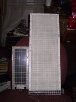 Big vs Small.jpg59.2 KB · Views: 593
 -
 TIG3.jpg136.1 KB · Views: 244
 -
 TIG2.jpg267.6 KB · Views: 248
 -
 TIG1.jpg140.1 KB · Views: 247
 -
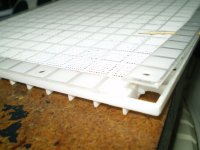
 Ready for The Diaphragm.jpg168.3 KB · Views: 244
 -
 ESL3.jpg60.4 KB · Views: 259
 -
 Botched Side All Fixed.jpg145.1 KB · Views: 517
 -
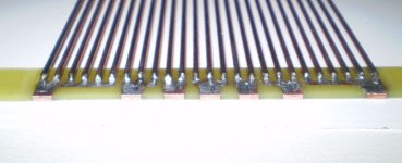 New Connection Method.jpg59.8 KB · Views: 525
 -
 Stator4.jpg492.9 KB · Views: 569
 -
 Stator1.jpg446.6 KB · Views: 585
Last edited:
Bolserst, this makes perfect sense. As I was experimenting, I ended up with 11 segments, which is what the rule of thumb formula would suggest for my fL of 200Hz. It also means my next panels (which I am shooting for much closer to full range) will need 22-25 segments. This will save many hours of trial and error!
My listening room is not large and high SPL is not a big factor for me, so I'll easily trade better dispersion for the lower efficiency.
My listening room is not large and high SPL is not a big factor for me, so I'll easily trade better dispersion for the lower efficiency.
I only have access to Excel at work so I had to wait until lunchtime today to open the spread sheet. OK, I punched in the numbers for my panel:
48" height, 10.5" width, .062 d/s, 200 Hz LF cutoff.
(this will be a bi-ampd hybrid ESL using a digital crossover for the woofer/panel crossover point at 220 Hz, 48db slope).
For the Symmetric Config 1 option, it looks like I would need to select an odd number of segments, with the center segment being 2x width of outer segments. But I don't have a good feel for now many segments (5,7,9,11) would be needed or preferable.
I'm wondering how many segments are good for my 10.5" wide panel. Any opinions?
Using the rule of thumb Bolserst supplied above, you would have the same as I did with a fL of 200hZ, 11 segments.
Using the rule of thumb Bolserst supplied above, you would have the same as I did with a fL of 200hZ, 11 segments.
OK... looks like I'm set. Just have to get the materials together and start.
Hi All
Wide segment do give rise to phase reversals and zeros, off axis, in upper registers of the audio band, - no doubt. But are they audible? Let me crunch some numbers.....
I based my recommendation of 12 mm segment width on an ideal ESL and ideal ears. At 20 kHz, the first zero in the polar response appears with 17 mm wide segments. There is of course some off-axis attenuation before the zero appears. Hence my suggestions of 12 mm, 15 mm max. Of course, few can hear these frequencies - dogs, bats, and young children - some teens.
However, for us older codgers with hearing cutting off at 13 kHz, we can scale those numbers to something like 25 mm max, ideally less than 20 mm.
Further, there has to be sustained (non-transient) musical content at those frequencies of a kind where we would notice the change in character of the sound as we move about. My guess is best test track is probably light jazz with drummer using a brush.
As Jer pointed out above, one has to consider power dissipation and voltage rating of the resistors too. Smaller segments allows the use of more resistors so you can spread the voltage and power out a bit.
best wishes
Rod
Oh Yes, do use an odd number, the segment in the middle must be the thinnest.
OK, now I'm confused: In the spread sheet, the symmetrical config 1 states that the first/center segment is equal to the sum of the outer segment pairs.
Please help me get this.
He is suggesting you use symmetric configuration 2 where all sections are of equal width.OK, now I'm confused: In the spread sheet, the symmetrical config 1 states that the first/center segment is equal to the sum of the outer segment pairs.
Please help me get this.
Note that you need to use different resistor values for the first few sections to get a flat response with this configuration.
If your segment width is less than 1" there isn't a lot to be gained from configuration 2.
But, if segment widths are > 1" you can get some improvement in top octave dispersion for angles > 15 degrees.
I tend to prefer configuration 1 because the dispersion trends are smoother and the RC line impedance is constant allowing use of same value resistors. Configuration 2 puts a kink in the trends, flattening out the response above 20Khz providing the improved off axis response mentioned above.
I have some comparison plots somewhere...will see if I can locate tonight.
Last edited:
How do you determine the number of wires per " respective to thier dia, ex 1/2" ready rod is 13 threads per ", 5/8 ready rod is 11 per ", .060 loks fine on 5/8, but is very closed on 1/2", wouldn't one be looking for 50% or more free area? and this is without paint buildup.
Al
Al
You shoot for something on the order of 50% open area. Using 035 rod at 50% means:
035 rod + say 004 paint = 039 solid
039 solid + 039 space = 078 period = 12.8/inch = 1/2" - 13 allthread.
035 rod + say 004 paint = 039 solid
039 solid + 039 space = 078 period = 12.8/inch = 1/2" - 13 allthread.
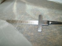
Here is an excerpt from my build page as I couldn't remeber exactly what my rod to rod spacing is,
"The rods are .0625" (62.5 mil) in diameter and the space in between each rod is set at .076" (76 mil).
My projected spacing was to be about .079" or 79 mil, but due to the error that was found in the previous post this shows the 3 mil difference.
This still allows me up to 10mil of coating thickness on each rod with an open area of 41.69%.
Typically I have found that 6mil to 8mil is all I will need to support 14kv or so of bias with a .072" (72 mil) D/S."
My actual coating thickness is slightly more at 10.5mil and this gives me a 40.57% open area with a .140" center to center spacing.
After I had built the panel all of the measurements were in spec using a micrometer and feeler gauges with my layout plan.
Had I used some .045" rod I could have gotten closer to %50 (46.42% actually) of open area like I wanted but I little less is okay as this will help to add a little dampening to the diaphragm.
I will try to find my layout plan and post it for you.
jer 🙂
P.S. I got lucky and found it Right Quick !! 🙂
Attachments

Last edited:
Had I used some .045" rod I could have gotten closer to %50 (46.42% actually) of open area like I wanted but I little less is okay as this will help to add a little dampening to the diaphragm.
My experience with perf-metal panels bears this out too. In fact, I prefer that the open area be 40%-45% and no higher. This build will be rather more that that so I may have to do something more to dampen the diaphragm.
Is there an advantage in choosing one configuration over the other?
With respect to acoustic response, as long as you are using a large number of segments, there is actually not much difference between the two configurations. If you are trying to minimize the number of segments, Configuration 2 will give you better off-axis response as golfnut mentioned.
With respect to physical construction, Configuration 2 may be easier to build since each electrical segment would be the same size. However, it requires different/specific resistor values for the first few segments to flatten the response. It may simply come down to what number/spacing of wires fits evenly on your stators.
I couldn’t locate the comparison plots I was thinking of, so I made a set for your project:
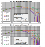
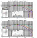
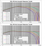
Attachment #1: Top plot compares 12 segments .vs. 24 segments. You can see that there is no difference below 10 Khz and only very minor improvement at 20kHz even out at 30 deg. The bottom plot shows a similar comparison with 12 segments .vs. 6 segments. You can see the out of phase lobing showing up in the top octave at 30 deg.
Attachment #2: Top plot compares 12 segments Config 1 .vs. Config 2. Again You can see that there is no difference below 15 Khz and only very minor improvement at 20kHz even out at 30 deg. You can see the kink in the response I mentioned previously. In this case, it is above 20Khz so not really a concern. The bottom plot compares 24 segments Config 1 .vs. 12 segments Config 2.
Attachment #3: Top plot is a repeat of the top plot from Attachment #1. The bottom plot is a comparison for the full range design SyBorg is contemplating. You can see that the rule of thumb for segment number holds up for fL=200Hz, and fL=50Hz. Notice the improvement in dispersion when fL is lowered...the drawback being SPL/sensitivity is lowered as well.
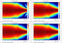
Attachment #4: A set of 4 sonograms for the configurations shown in Attachment #1 & #2. Notice the out of phase lobing behavior with 6 segments. Moving from 6 to 12 segments shows a marked improvement. Going to 24 segments shows only minor improvement at 20Khz and angles > 30 deg. With 12 segments, Configuration 1 or 2 show only minor differences and only at 20Khz for angles > 30 deg.
Attachments
Last edited:
There was a study a while back in one of these threads about using some fine mesh silk screen covers for dampening.
I had Mom get some of that really fine material used for Window curtains but I haven't had the chance to try it yet.
I have no idea what its mesh number is, I think she told me but I forget what it is.
It may be around 90 to 110 per inch. 🙂
jer 🙂
I had Mom get some of that really fine material used for Window curtains but I haven't had the chance to try it yet.
I have no idea what its mesh number is, I think she told me but I forget what it is.
It may be around 90 to 110 per inch. 🙂
jer 🙂
Attachments
Last edited:
- Status
- Not open for further replies.
- Home
- Loudspeakers
- Planars & Exotics
- Thinking about a segmented wire stator ESL