Hello!
I've just bought a non-working Theta DSP GenV (symmetrical version, end of 1995). The only thing I knew before I bought it was that one channel was sizzling (not working) and one channel ok. I never had the opportunity to listen to a Theta product and I get tempted to have one along my ML36, Wadia X32, 16 and Krell KAV 300CD. To be able to compare, I needed one.
But before that, I've got to fix it!
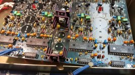
Here's a picture of the Digital Input and DA conversion boards showing that only the left channel seems to be working (red led lit). The right channel isn't operational since the led is unlit.

We can see that there has been already some "work" done on this board. I guess someone had problems unsoldering and/or soldering components, particularly on the right channel (left side of the picture...). I've made some quick measurements on different places on this specific part of the board, just with the Fluke. No or almost no power near or around the - side of differential right output. The LM337 neg regulator is at 0V on pin 2 (I out), so are the AD707 AOP and the R203 10k resistor as shown below (part of a drawing I made to remember where all wires go - before unsoldering - and to make measurement easier):

I also checked some capacitors in circuit (before I can take that board out and free) and one of the 470µF/16V (C719) is notably out of specs with an ESR > 40 Ohm, couldn't check properly the other ones I prefer to take them out (and anyway I'll replace them all since this DAC is 30 years old and it's probably useful to have this done preventively). But before anything, I'll have to replace that capacitor and similars.
Nevertheless a few points seem curious to me:
I'll keep you informed.
Thanks for reading!
I've just bought a non-working Theta DSP GenV (symmetrical version, end of 1995). The only thing I knew before I bought it was that one channel was sizzling (not working) and one channel ok. I never had the opportunity to listen to a Theta product and I get tempted to have one along my ML36, Wadia X32, 16 and Krell KAV 300CD. To be able to compare, I needed one.
But before that, I've got to fix it!
Here's a picture of the Digital Input and DA conversion boards showing that only the left channel seems to be working (red led lit). The right channel isn't operational since the led is unlit.
We can see that there has been already some "work" done on this board. I guess someone had problems unsoldering and/or soldering components, particularly on the right channel (left side of the picture...). I've made some quick measurements on different places on this specific part of the board, just with the Fluke. No or almost no power near or around the - side of differential right output. The LM337 neg regulator is at 0V on pin 2 (I out), so are the AD707 AOP and the R203 10k resistor as shown below (part of a drawing I made to remember where all wires go - before unsoldering - and to make measurement easier):
I also checked some capacitors in circuit (before I can take that board out and free) and one of the 470µF/16V (C719) is notably out of specs with an ESR > 40 Ohm, couldn't check properly the other ones I prefer to take them out (and anyway I'll replace them all since this DAC is 30 years old and it's probably useful to have this done preventively). But before anything, I'll have to replace that capacitor and similars.
Nevertheless a few points seem curious to me:
- Some power supplies are indicated on the PCB as +50 & -50V but don't go over 40V, is it like it should be?
- The filtering caps around these rails are (only) 50V, less than 20% over the 40V rails of point 1. I intend to replace them with 63V 105°.
- The board is quite thin and rather souple (1,4mm), is it what is called Teflon board? The dig input board is FR4 standard 2,5, normally rigid.
- I've not investigated the power board yet, since all wires coming from it seems to convey the right tensions. I'll replace caps too, maybe reinforce the bridges as they seem to get hot easily.
I'll keep you informed.
Thanks for reading!
Last edited:
And I wonder if it would be a good idea to:

- install board-to-wire connectors for the 6 wires (x2) digital to analog board. These are 2,54mm pitch 2 rows 16 positions. This would make disconnection (for work) easier. Would it be was good a connection as soldering?
- in the same vein, have the 4 AOP on (good quality) DIP sockets? to avoid unsoldering/soldering several times if they fail...
HIThis is my physical drawing
Can you post this schematic in better resolution?
Hi I’m redrawing it with the real values which are on my own board. Just a few days to wait.

And I wonder if it would be a good idea to:
- install board-to-wire connectors for the 6 wires (x2) digital to analog board. These are 2,54mm pitch 2 rows 16 positions. This would make disconnection (for work) easier. Would it be was good a connection as soldering?
I wouldn't do that. These are sensitive clock signals and they used shielded cable for transmission.
I think you're right @canvas, that's why I asked... Thanks for your response anyway.
One can find shielded connectors, but the contact may not be as close and of adequate quality. I won't do that so.
And replacing the soldered wires for voltage supply with connectors, even if more practical for operating on the board, isn't easy because of the small space under the board. And I guess this topography was engineered by Theta in a way that there would be no interference (or less) between power wires and small signal voltages on the board... I'm not an expert at all and I'm confident in the fact they know what they designed and why!
Hi everybody, here's my transcription of the differential output circuit. I'll add the single-ended part later. The previous schematic mixed up, I think, some resistors and capacitors. That's the reason why it's somewhat different. I hope I didn't mix up components or anything else myself, and that you'll find some logic in the drawing. I hope the resolution is good enough, if not I can make a better pdf.
Some MLCC caps are written 10K0 or 5K00, I'm not sure of their value. I guess it's in pF, but help will be appreciated from people who know!
I'm welcoming suggestions of course, because I'm not engineer or expert -at all. This schematic helps me to understand and repair - hopefully - that beautiful DAC.
Attachments
I must say I'm surprised by the extreme precision, (and uncommonness) of some resistors value... 634Ω, 33,2Ω, 4,99Ω... and even a 41pF capacitor.
Theta engineers didn't choose these values by chance I suppose... and I doubt it's because they had only these in stock. Would it be part of the secret for the legendary musicality of this machine?
Theta engineers didn't choose these values by chance I suppose... and I doubt it's because they had only these in stock. Would it be part of the secret for the legendary musicality of this machine?
Hi, not sure I can do that for all. I could do it for some caps when the marking is usual: 41H, 105, 106 etc., but not for the 5K00 or 1K50 since I don't know this particular coding. And I guess the values are too small for my DMM... if they are in the pF range as I think. That's why I was asking if someone knows about that particular marking.
I'll ask a friend of mine who is an old tech and 1) maybe he's got a dedicated and precise capacimeter 2) maybe he'll know about this marking code 3) maybe he can guess the values from their place.
And I'll go on searching myself!
By the way I added a few things on the schematics since yesterday, but I'll go on with the asymmetrical output this weekend and I'll post the last one later, if you can wait.
😉
Could they be resistors? Do you have a close-up high-res pic? From the schematic it might make more sense.Some MLCC caps are written 10K0 or 5K00...
This is exactly the reason why i asked to measure these elements....Could they be resistors?
look at this:
photo posted by dtm1962 in post#18
I have marked in red the elements that raise our doubts
On the PCB they are marked as R, which means resistance!
Easy to check by DMM !
I think these are precision resistors, which explains their unusual values.
I think I have seen similar resistors in the form of a "drop"
Attachments
You're all so right! And I'm so confused to have missed that!
I never saw such resistors before and they looked so much like MLCC capacitors (small yellow drop cases) that I didn't even measure them. So I did 10' ago, and they are resistors, right!

So now my schematic is (nearly) completely wrong and I apologize sincerely to all for that stupid mistake!
I'll keep in touch with new drawings. By the way I must be a little confused, we had our 15 years old cat euthanized today and I won't do much tonight. Sorry once again...
I never saw such resistors before and they looked so much like MLCC capacitors (small yellow drop cases) that I didn't even measure them. So I did 10' ago, and they are resistors, right!
So now my schematic is (nearly) completely wrong and I apologize sincerely to all for that stupid mistake!
I'll keep in touch with new drawings. By the way I must be a little confused, we had our 15 years old cat euthanized today and I won't do much tonight. Sorry once again...
I add that I started to desolder the caps (1000, 470, 220µF...) and the 4 I took out were totally out of original values and ESR sometimes > to 40 ohm... So all of them has to be replaced, for sure.
I asked if the board was a teflon one because 1) it's much thinner and less rigid than the classical FR4 boards 2) the green mask is very fragile to heat. Not easy to take out components properly I must say, even with a Metcal desoldering gun. And the vias come out easily. Too easily ;(
I asked if the board was a teflon one because 1) it's much thinner and less rigid than the classical FR4 boards 2) the green mask is very fragile to heat. Not easy to take out components properly I must say, even with a Metcal desoldering gun. And the vias come out easily. Too easily ;(
If you have a moment, could you take a picture of the PCB - the bottom side ?
I'm very sorry about your cat. Mine is 12 years old.
I'm very sorry about your cat. Mine is 12 years old.
Here is it Zoltan (and thanks for your thoughts, I appreciate):

You can see it has been already worked... I hope I can do no more harm to it.
You can see it has been already worked... I hope I can do no more harm to it.
These resistors are (very) high-precision Bulk Metal® Foil resistors from Vishay. Datasheet here: https://www.mouser.fr/datasheet/2/428/VSH_VSC-3247332.pdf
- Home
- Source & Line
- Digital Line Level
- Theta Gen V DAC Output Stage Issue: SCHEMATIC Anyone?