What solder do you use?
60/40 tin/lead should do fine at 400 - 450 deg. C.
Forget about the fancy lead free solders, pretty useless.
Also the tip, what size, temperature is not everything when soldering.
These tags will need some chunky tip and maybe a bit of tinning beforehand.
60/40 tin/lead should do fine at 400 - 450 deg. C.
Forget about the fancy lead free solders, pretty useless.
Also the tip, what size, temperature is not everything when soldering.
These tags will need some chunky tip and maybe a bit of tinning beforehand.
T12 station at 420 at the moment with a big ish chisel tip. Old fashioned pb solder but unsure of constitution. They really struggle to 'wet'..solder .just runs off or blobs together. Its like there's a coating of something on them. Assuming they are solid copper/brass as filing them remains the same colour. Using liquid flux . I'm not new to soldering although I will accept advice gratefully which I do comments above....thanks.....I shall turn the iron up to full tilt and see!
Thanks guys ...everyday is a school day. I'm surprised how hot I need to get them.....430 to 450 does the trick. Im just making sure to solder them on first so the heat doesn't conduct into the next component inline.
Cheers!
Cheers!
Are you sure they are meant for soldering? There is a great amount of force on engaging/disengaging, and there is no strain relief. Those things will not hold for long on the PCB. They will become loose, however well you solder them.
Good comment...First time I used them they pulled straight off of the pcb.....before I got them hot admittedly.
How else would these be mounted.?
How else would these be mounted.?
They do require a lot of heat but once properly Soldered I haven’t had long term durability issues. Long term being like ten years in a home environment... the equipment isn’t getting a lot of mechanical shock.
Try some wool or sandpaper before soldering.
If they aren't meant for solder, I've seen many amps that use these types. And Yes they come loose if You wiggle them. You could perhaps bend the tips on the other side of the PCB for strain relief, but depends on thickness.
If they aren't meant for solder, I've seen many amps that use these types. And Yes they come loose if You wiggle them. You could perhaps bend the tips on the other side of the PCB for strain relief, but depends on thickness.
Are you sure they are meant for soldering? .
I checked the part number and they are for soldering. Not that I have ever tried to solder press fit connectors and wondered why they didn't hold well 🙂
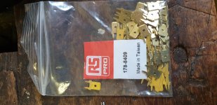
Look like PCB solder faston type terminals to me, used similar parts a few times.
However if they are for high current use there may be a lot of copper connected on the PCB. This can sink the heat away as you are soldering making it difficult (i.e. not the parts fault).
That is assuming you are mounting them on a PCB.
If you suspect them then try "soldering" one out of the PCB, with just the terminal with an iron on it (even a low power iron) should heat up quickly and accept solder.
And, as per a previous post, make sure you are using a decent iron for this. 50W would seem like a minimum, that's what I have used with these type of terminals, but it can take a while to get the heat into a PCB, so higher power would be better.
An old-reliable Weller 100/140W gun comes in mighty handy for parts like these with greater thermal inertia.
The tails of those look to me like they're designed to be 'swaged' (if I'm spelling that correctly -- rhymes with 'wedged'). Maybe they make a tool that drives both pins away from the centerline firmly (struck with a hammer) and at the same time. Then the solder only has to provide the electrical connection. Then the only problem is, cracked solder can cause the connection to become intermittent without becoming obviously loose.
Cheers
Last edited:
Member
Joined 2009
Paid Member
Yup, needs a big iron.
I find half the battle is getting heat from the iron onto the cold metal, a dry iron just has no effective contact area to transfer heat, it needs to be ‘wet’ with molten solder.
I start with melting a blob of solder on the board metal near to, but not touching the pin of the lug which otherwise will suck all the heat out and freeze the blob - make a molten blob on the pcb pad/trace first to create a good thermal contact between an otherwise dry iron and cold metal, then add solder and grow the molten blob to the lug, let the lug start to suck heat, move the iron / add fresh solder to keep a good mass of hot solder to transfer heat, don’t let it freeze, when the lug is hot enough you can push the iron onto the lug keeping the solder molten and feed more fresh solder to create the joint. Small irons need not apply.
Last edited:
Are you sure they are meant for soldering? There is a great amount of force on engaging/disengaging, and there is no strain relief. Those things will not hold for long on the PCB. They will become loose, however well you solder them.
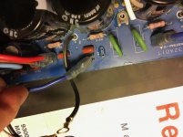
Here's one that got pulled out from an Adcom 5400 PS board, so fair warning!
Attachments
Thanks guys yes heat is the key here...live and learn. Didnt think there was that much heat inertia in these things but obviously so . There on speaker crossover boards so no high voltage worries and shouldn't be disconnected very often at all
The trick is to walk/wiggle the connector instead of just pulling on it. Also, roughing up the solder pins with course sandpaper will give the solder a texture to bite into making it less likely to pull out. At least in theory - that's why you key a surface to make paint stick to it better, right?
And keep the walk/wiggling to within the approximate plane containing the male tab's major dimensions. That reduces the leverage to pop the solder joints.
Regards
Regards
- Home
- Design & Build
- Parts
- These things WILL NOT solder