Hi,
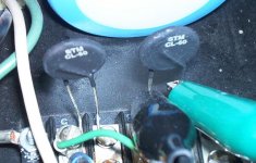
I'm using a pair of CL-60's and I measured them just over 10 ohms prior to installing them before the transformer, like 2 months ago.
I checked them with my multimeter immediately after power down today, and found that they measured around 2 ohms.
I turned off the amp and after like 5-10 minutes, they slowly reached up to 5 ohms but never returned to the original measurement.
It took like 6 hours for them to get up to about 5.7 ohms. I tested an 8ohm resistor I had lying around to see if something else was off, but my multimeter measured it just fine.
Is it normal for these devices to go out of spec?
The next thing I tried was leaving the multimeter connected across the thermistor, turned the amp on and turn up some music for a minute or 2. I got a voltage reading (slightly varying) of approx 2v AC. (us voltage 120v)
Any thoughts or input on this would be appreciated -thx
In order to evaluate a thermistor you must measure the temperature as well as the resistance, and make sure the resistance measurement isn't affecting the temperature.
I have no idea what CL-60s are. When you mention a model number, ALWAYS also mention the manufacturer. Don't assume we know what you are talking about.
I have no idea what CL-60s are. When you mention a model number, ALWAYS also mention the manufacturer. Don't assume we know what you are talking about.
GE SENSING / THERMOMETRICS|CL-60|Thermistor | Newark.com
How much current are you running trhrough it?
How big is your transformer? Has it a dual primary winding?
How much current are you running trhrough it?
How big is your transformer? Has it a dual primary winding?
Last edited:
The CL-60's are Digikey part#KC006L-ND (similar to the GE example above)
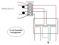
They are current inrush limiters. I am using them on the dual primary windings going into a PS Audio 200c.
Known ratings: 200w x 2 @8ohms/1000w x2@1.5ohms
Transformer: Hi-Pot tested @ 2.5KV, EI type. 2pair of primary windings fed from 120v US, 3 pair of secondary: +57/-57, 0/0, +57/57. The large capacitors are 10000uf x2 per channel.
I wanted to lower the arcing at turn on for the Relay = Magnecraft W199AX-9(40A).
The original design suggested the BIG blue flash was normal, and to leave the amp on 24/7. But the amp is old (1986) and I'm hoping to get more life out of it (plus I don't want to keep it on 24/7)
The thermistors indeed lower the arcing to next to nothing, and the amp works fine. But I wonder if these thermistors will ever go back to a cold 10ohms and I don't think they will at this point.
Or maybe...I'm measuring them incorrectly? The 5.7 ohm reading is measuring from the leads while they are installed.
Attachments
Last edited:
You mean 57v ac x 2? (57v ac give about 80v dc)
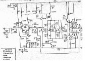
What is that shorted secondary winding 0/0? There must be a mistake here.
...
Anyway,
I think cl60 is quite small for this big transformer. The peak must be huge at powering on.
This thermistor is generally used with smaller transfos.
I would try 2x cl60 in series with each primary winding in order to reduce the peak. Or use a soft start. The relay being already there.
I use cl 60 with 250va transformers, it works fine though i never measured it after duty .
A condenser across the contacts of the relay could help to reduce the spark too.
Last edited:
You mean 57v ac x 2? (57v ac give about 80v dc)
What is that shorted secondary winding 0/0? There must be a mistake here.
...
Apologies, my vocabulary in electronics is limited.The 2 pair of windings prior to rectification would be +57/-57 volts AC. The center pair is paralleled and goes to a chassis grounded bus-bar. Indeed this would provide 80vdc after rectification (75vdc is needed for each channel). I think I'm saying this correctly?
I think cl60 is quite small for this big transformer. The peak must be huge at powering on.
This thermistor is generally used with smaller transfos.
I would try 2x cl60 in series with each primary winding in order to reduce the peak. Or use a soft start. The relay being already there.
I use cl 60 with 250va transformers, it works fine though i never measured it after duty .
A condenser across the contacts of the relay could help to reduce the spark too.
Well that makes some sense, but according to that GE link on suggested usage, based on capacitance, I would need like 2 per cap = 8 x CL-60's. Then again, my arrangement looks nothing like the model. The arrangement I'm using is like the Nelson Pass burning amp, prior to the transformer, not after rectification.
Calculating the exact values seems like a daunting task. However, while I'm not quite sure what the maximum in-rush is, the maximum steady state current of 5 amps each seems reasonable. They still seem to minimize the turn-on flash and are hardly warm to touch even when the amp has been on for a week+. What's the worse that can happen, one breaks? Maybe I should take one out and measure it outside the amp.
Interesting thought on the condenser, I'll have to look into that.
Last edited:
Thermistors on primaries are enough.
The inrush of an EI transfo is not as huge as the inrush of a torroidal one.Though yours is really big. (it must weigh a ton)
When the amp is at idle or playing not loud, the current drawn is little, that is why the thermistors do not really heat.
Yes, unsolder one to measure it.
A condenser of about 0.01uf /250v across the contacts should reduce the sparkle.
Thermistors in primary windings makes the transfo surge smaller, avoiding to blow the main fuse.
Thermistors in secondary windings avoids overloading the rectifier when caps are charging. It is sometimes used in class A amps where capacitor values are high. Which is not your case.
When i say 2 cl 60 in series, it is to make the resistor larger, not for current purpose.
Thermistors in secondary windings avoids overloading the rectifier when caps are charging. It is sometimes used in class A amps where capacitor values are high. Which is not your case.
When i say 2 cl 60 in series, it is to make the resistor larger, not for current purpose.
Last edited:
I took out the thermistor and re-measured it. As it turns out the device is fine, I didn't account for paralleled resistance, which is why I got the low reading.
When I measured resistance across one, I was actually picking up the parralelled resistance of both.
I think they heat up just fine at Idle, dropping resistance almost instantaneously.
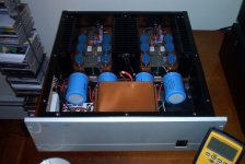
And yes, the transformer is pretty huge for this type, weighs almost 30 pounds.
When I measured resistance across one, I was actually picking up the parralelled resistance of both.
I think they heat up just fine at Idle, dropping resistance almost instantaneously.
And yes, the transformer is pretty huge for this type, weighs almost 30 pounds.
Attachments
Last edited:
So, everything is fine.
It's quite a rule to unsolder one end when mesuring resistors.
Nice amp!
Though, the power rating on low loads is optimistic.
2x1000w@ 1.5 ohms is not possible using three pairs of 12A / 150w devices.
It's quite a rule to unsolder one end when mesuring resistors.
Nice amp!
Though, the power rating on low loads is optimistic.
2x1000w@ 1.5 ohms is not possible using three pairs of 12A / 150w devices.
The thermistors simply replaced the screw down jumpers on the distro block, so I just made the ends into tight eyelets and screwed them down in place. They sit in place just right
Thanks, it's kind of cool looking I think. The sound is extraordinary.
As far as the power ratings go, I'm just going with the manufacturers rating on this.
I don't know whats possible with a 2SB600/2SD555 combo x 6.
From Stereophile:
Sidebar: Specifications
Description: Solid-state, stereo power amplifier. Inputs: direct-coupled (DC), capacitor-coupled. Output power: >200Wpc into 8 ohms, 400Wpc into 4 ohms, 1000Wpc into 1.5 ohms. Peak current: 64A. Bandwidth: DC to 140kHz, -3dB. Damping factor: >400. S/N Ratio: >100dB. Slew rate: 300V/ms. Rated THD: 0.02%. Rated IMD: 0.01%. Sensitivity: 1.3 volts for rated output.
Dimensions: 19" W by 6½" H by 19" D. Weight: 70 lbs.
Serial number of review sample: 1024.
Price: $1649 (1985).
Peace
I don't know whats possible with a 2SB600/2SD555 combo x 6.
I thought it was 3 pairs, like on shematic, sorry.
The specs are impressive!
This amp should not fear difficult loads. I will keep the schematic in my list.
Thank you.
Have fun.
Ah I dunno, somethin still seems odd. The schematic is for 1 channel, so that their are actually 3 pairs of 2SB600/2SD555. You said they we're 150w devices, which to me means what 6 x 150 = 900w/channel? I've seen them spec'd out at 200w each which might make sense as an absolute max but I can't imagine the amp would last long used that way.
So the 1000w x 2 might be truly optimistic but not very realistic as you say.
But then again I don't know what any of it means 100% -lol
peace
So the 1000w x 2 might be truly optimistic but not very realistic as you say.
But then again I don't know what any of it means 100% -lol
peace
Taking into account that speakers are reactive loads and the possibility for the heatsinks to get warm, I would evaluate about 150w/ 4 ohms/ pair in order to stay within SOAR limits.
according to this post ( last lines) :
http://www.diyaudio.com/forums/soli...sistor-safe-operating-area-4.html#post2049155
These calculators -made for MJL21193- gives an idea. (count 2 MJL for3 devices like yours)
http://www.diyaudio.com/forums/soli...sistor-safe-operating-area-5.html#post2053242
Though, in a home environnement, if you keep the heatsinks cold, you can get more instantaneous power than that.
I would not hook speakers of less than 4 ohms.
Last edited:
In fact, using the calculators:
+/-80v supply
sagging at 70v under load at max power
8 ohms load
45° phase shift (reactive load)
0.1 ohms emmitor resistors
2 pairs of MJL (16A / 200w)
We already run out of soa curve. ( green) @306w rms
The limiters have to do their duty.
+/-80v supply
sagging at 70v under load at max power
8 ohms load
45° phase shift (reactive load)
0.1 ohms emmitor resistors
2 pairs of MJL (16A / 200w)
We already run out of soa curve. ( green) @306w rms
The limiters have to do their duty.
Last edited:
- Status
- Not open for further replies.
- Home
- Amplifiers
- Solid State
- Thermistor spec changes?