For some time I am trying an amp with TermalTrak ON semiconductor. I included TMC too and here is what I came up to now.
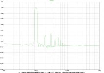
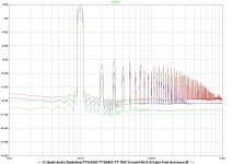
I simulated it with LTSpice and the results are here.
THP at 1kHz is 0.000011% and at 20kHz is 0.000186%.
I did PCT with Sprint Layout and tested it with my test bench power supply +-30V up to 2A.
I did not test it with +-50V for what it was designed.
The bias seams to be stable, it did not change from 20deg C to 50deg C.
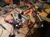
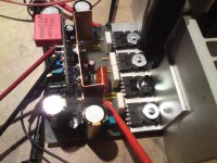
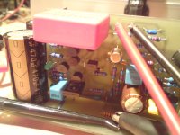
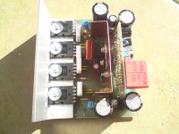
This is just proto board, main board and small input board. I intend to mak all in one board, it was for testing porpoises. It was not tested with a musik jet, no power supply redy jet.
dado
OITCP(Output Inclusive Two Pole Compensation) used in this TT amp instead of TMC. http://www.diyaudio.com/forums/solid-state/182554-thermaltrak-tmc-amp-60.html#post4466147 page 60, post #594
Album with the amp construction created: http://www.diyaudio.com/forums/gallery/showgallery.php?cat=2246
I simulated it with LTSpice and the results are here.
THP at 1kHz is 0.000011% and at 20kHz is 0.000186%.
I did PCT with Sprint Layout and tested it with my test bench power supply +-30V up to 2A.
I did not test it with +-50V for what it was designed.
The bias seams to be stable, it did not change from 20deg C to 50deg C.
This is just proto board, main board and small input board. I intend to mak all in one board, it was for testing porpoises. It was not tested with a musik jet, no power supply redy jet.
dado
OITCP(Output Inclusive Two Pole Compensation) used in this TT amp instead of TMC. http://www.diyaudio.com/forums/solid-state/182554-thermaltrak-tmc-amp-60.html#post4466147 page 60, post #594
Album with the amp construction created: http://www.diyaudio.com/forums/gallery/showgallery.php?cat=2246
Attachments
-
DADO-TT-TMC.pdf21.1 KB · Views: 2,325
-
DADO-TT-TMC_fft.pdf105.5 KB · Views: 795
-
DADO-TT-TMC_fft10.pdf184.1 KB · Views: 573
-
DADO-TT-TMC_fft20.pdf177.5 KB · Views: 508
-
DADO-TT-TMC_nfb.pdf40.8 KB · Views: 658
-
 DSC01441.JPG847.8 KB · Views: 5,715
 -
 DSC01442.JPG854.9 KB · Views: 5,207
 -
 DSC01443.JPG860.8 KB · Views: 4,798
 -
 DSC01444.JPG881.2 KB · Views: 4,436
 -
 DSC01445.JPG765.6 KB · Views: 4,088
Last edited:
ThermalTrak+TMC
No comments at all??
It was nice to find how is easy to go so low in THD below ppm with this quite simple schematic.
Input is cascoded LTP with LSK389 in metal TO71 from Linear Systems. First CCS gives cca
No comments at all??
It was nice to find how is easy to go so low in THD below ppm with this quite simple schematic.
Input is cascoded LTP with LSK389 in metal TO71 from Linear Systems. First CCS gives cca
ThermalTrak+TMC
Sorry for previous post, I sent it accidentally.
The first CCS is cca 9mA, and this is 4mA per each side of the LTP. 1ma is for cascode to keep cca 10V on JFETs.
The bias control is ddivided between ThermalTrak diodes and Vbe multiplier.
Vbe multiplier is thermally connected with the drivers only as suggested by Bob Cordel.
I was thinking to use a triple as suggested by Cordel for ThermalTrak in one of the ThermalTrak treads. I will do that probably later, never use triple before. Symulation does not show important improvement.
PCT in first post should be PCB off course.
Fourier components of V(vout) 1kHz
DC component:-0.0296359
Harmonic Frequency Fourier Normalized Phase Normalized
Number [Hz] Component Component [degree] Phase [deg]
1 1.000e+03 2.665e+01 1.000e+00 -0.13° 0.00°
2 2.000e+03 1.973e-06 7.402e-08 87.49° 87.62°
3 3.000e+03 2.029e-06 7.615e-08 11.10° 11.23°
4 4.000e+03 2.899e-07 1.088e-08 -41.62° -41.49°
5 5.000e+03 1.746e-07 6.550e-09 -15.60° -15.47°
6 6.000e+03 2.994e-07 1.124e-08 -7.33° -7.19°
7 7.000e+03 3.302e-07 1.239e-08 0.49° 0.62°
8 8.000e+03 4.099e-07 1.538e-08 -6.78° -6.64°
9 9.000e+03 4.130e-07 1.550e-08 -0.83° -0.70°
Total Harmonic Distortion: 0.000011%
Fourier components of V(vout) 20kHz
DC component:-0.029628
Harmonic Frequency Fourier Normalized Phase Normalized
Number [Hz] Component Component [degree] Phase [deg]
1 2.000e+04 2.663e+01 1.000e+00 -2.61° 0.00°
2 4.000e+04 2.881e-05 1.082e-06 96.30° 98.91°
3 6.000e+04 1.920e-05 7.208e-07 143.84° 146.45°
4 8.000e+04 1.628e-05 6.112e-07 -143.04° -140.44°
5 1.000e+05 2.368e-06 8.890e-08 -34.05° -31.44°
6 1.200e+05 1.431e-05 5.375e-07 -150.17° -147.56°
7 1.400e+05 1.741e-05 6.536e-07 145.16° 147.76°
8 1.600e+05 1.129e-05 4.241e-07 -148.10° -145.49°
9 1.800e+05 1.883e-05 7.072e-07 137.23° 139.84°
Total Harmonic Distortion: 0.000186%
dado
I simulated it with LTSpice and the results are here.
THP at 1kHz is 0.000011% and at 20kHz is 0.000186%.
dado
Simulated THD figures are far from reality. Better show real world prototype measurements.🙂
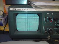
I've got a tone generator (sinus no better then 0,5%) an oscilloscope and 8/4 ohm load.
With that I can't get any valide THD measurements. I will show square wave measurements on 8/4 ohm//1nF-1uF load to show stability when I finish +-50V 500VA power supply.
dado
With that I can't get any valide THD measurements. I will show square wave measurements on 8/4 ohm//1nF-1uF load to show stability when I finish +-50V 500VA power supply.
dado
TT+TMC Slew Rate improvement as suggested by D. Self
To improve Slew Rate I change CCS-s according to D. Self.
That I did in LTSpice only.Intereting is when change was made that controling CCS to be VAS CCS instead LTP CCS as in build protype the THD at 20kHz increased threefold.
Then, when I added small capacitor of 6pF(D. Self suggestion) between CCS collector and base of the controlling transistor, it incresed dramatically. Is it worth to increment slew rate and in the same time the THD???
D. Self CCS
Fourier components of V(vout)
DC component:-0.0310529
Harmonic Frequency Fourier Normalized Phase Normalized
Number [Hz] Component Component [degree] Phase [deg]
1 2.000e+04 2.663e+01 1.000e+00 -2.63° 0.00°
2 4.000e+04 9.475e-05 3.558e-06 136.72° 139.34°
3 6.000e+04 1.843e-05 6.918e-07 148.38° 151.00°
4 8.000e+04 1.602e-05 6.014e-07 -143.55° -140.93°
5 1.000e+05 1.573e-06 5.907e-08 -38.79° -36.17°
6 1.200e+05 1.443e-05 5.419e-07 -150.26° -147.63°
7 1.400e+05 1.813e-05 6.807e-07 145.10° 147.73°
8 1.600e+05 1.126e-05 4.229e-07 -148.17° -145.54°
9 1.800e+05 1.934e-05 7.261e-07 137.05° 139.67°
Total Harmonic Distortion: 0.000387%
D. Self CCS with 6pF
Fourier components of V(vout)
DC component:-0.0322834
Harmonic Frequency Fourier Normalized Phase Normalized
Number [Hz] Component Component [degree] Phase [deg]
1 2.000e+04 2.663e+01 1.000e+00 -2.63° 0.00°
2 4.000e+04 1.196e-03 4.492e-05 -108.97° -106.34°
3 6.000e+04 2.318e-05 8.705e-07 -178.36° -175.74°
4 8.000e+04 1.662e-05 6.242e-07 -144.68° -142.06°
5 1.000e+05 1.330e-06 4.995e-08 -34.05° -31.42°
6 1.200e+05 1.484e-05 5.573e-07 -151.23° -148.60°
7 1.400e+05 1.890e-05 7.095e-07 144.09° 146.72°
8 1.600e+05 1.144e-05 4.294e-07 -149.40° -146.77°
9 1.800e+05 2.003e-05 7.521e-07 136.16° 138.78°
Total Harmonic Distortion: 0.004495%
Here you can use my LTSpice simulation.
DADO-TT-TMC-new is D. Self CCS
dado
Attachments
By the time Self published edition 2 of his power amplifier book, his writings on slew rate had become confused and he reached no conclusion other than he could not solve the asymmetrical slew rate, problem.
Read Cordell and many others for info on slew rate.
Read Cordell and many others for info on slew rate.
In the 5th edition D. Self suggests to use (figure 8.49) small Cs=6pF with result +42 -43 V/usec. I simulated it in LTSpice attached in previous post, but I have got to much distortion as result. Schematic is DADO-TT-TMC-new when unzip the file.
dado
dado
Amp powered up and some listening
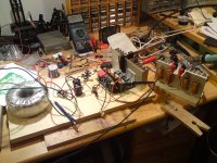
I have powered up this amp from +-50V temporary power supply. You can see it on the photo.
I was listening it for short time, only one chanell, in mono. Sound was good and clear. I need stereo set up to evaluate it more accurately.
With 0.1 ohm as emiter resistor the bias increased for 17% from 25 degree C to 50 degree C.
With 0.22 ohm it increase for 15% for the same change in temperature.
I run it without input signal and no heathsink, only alu bracket. Output transistor temerature slowly increased from 25 to 50 degree C just run with bias current and at that point I switched off the power.
For 0.1 ohm I adjusted the voltage to 13mV, means bias current to 130mA, and it increased to 17mV at 50 degree.
For 0.22 ohm it was 20mV and it increased to 23mV (from 90mA to 105mA.
I think it is qute good result.
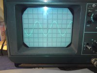
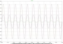
After that I connected amp to signal generator (quite high disstortion about 1%)
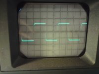
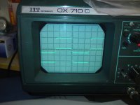
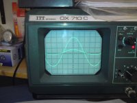
On the scope screen are two sinus signals input(lower amplitude) and output on 8 ohm.
Here is also sinus klipping where is visible TMC type of klipping.
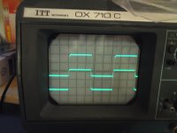
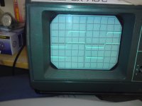
With the square signall there are the photos at 1kHz and 20kHz without and with capacitor parallel to he load. First with 10nF and then with 0.1uF.
dado
I have powered up this amp from +-50V temporary power supply. You can see it on the photo.
I was listening it for short time, only one chanell, in mono. Sound was good and clear. I need stereo set up to evaluate it more accurately.
With 0.1 ohm as emiter resistor the bias increased for 17% from 25 degree C to 50 degree C.
With 0.22 ohm it increase for 15% for the same change in temperature.
I run it without input signal and no heathsink, only alu bracket. Output transistor temerature slowly increased from 25 to 50 degree C just run with bias current and at that point I switched off the power.
For 0.1 ohm I adjusted the voltage to 13mV, means bias current to 130mA, and it increased to 17mV at 50 degree.
For 0.22 ohm it was 20mV and it increased to 23mV (from 90mA to 105mA.
I think it is qute good result.
After that I connected amp to signal generator (quite high disstortion about 1%)
On the scope screen are two sinus signals input(lower amplitude) and output on 8 ohm.
Here is also sinus klipping where is visible TMC type of klipping.
With the square signall there are the photos at 1kHz and 20kHz without and with capacitor parallel to he load. First with 10nF and then with 0.1uF.
dado
Attachments

I think your LTP degeneration resistors are too large for Jfets, the noise contribution from there will probably be higher than the THD. You shoulnt go higher than 22 ohms and that is pushing it.

I think your LTP degeneration resistors are too large for Jfets, the noise contribution from there will probably be higher than the THD. You shoulnt go higher than 22 ohms and that is pushing it.
You quite right.
I simulated now with 100, 47 and 22ohm for LTP degeneration resistors at 20kHz.
Harmonic Frequency Fourier Normalized Phase Normalized
Number [Hz] Component Component [degree] Phase [deg]
1 2.000e+04 2.663e+01 1.000e+00 -2.61° 0.00°
2 4.000e+04 2.516e-05 9.446e-07 94.06° 96.67°
3 6.000e+04 1.830e-05 6.872e-07 51.00° 53.61°
4 8.000e+04 2.071e-05 7.777e-07 -140.51° -137.90°
5 1.000e+05 2.371e-05 8.903e-07 4.00° 6.61°
6 1.200e+05 2.488e-05 9.343e-07 -139.66° -137.05°
7 1.400e+05 1.931e-05 7.251e-07 137.76° 140.36°
8 1.600e+05 2.865e-05 1.076e-06 -134.64° -132.03°
9 1.800e+05 4.145e-05 1.556e-06 152.18° 154.79°
Total Harmonic Distortion: 0.000278% 100ohm
Harmonic Frequency Fourier Normalized Phase Normalized
Number [Hz] Component Component [degree] Phase [deg]
1 2.000e+04 2.664e+01 1.000e+00 -2.12° 0.00°
2 4.000e+04 1.766e-05 6.628e-07 89.11° 91.23°
3 6.000e+04 1.115e-05 4.185e-07 52.87° 54.99°
4 8.000e+04 1.317e-05 4.942e-07 -136.29° -134.17°
5 1.000e+05 1.512e-05 5.677e-07 9.02° 11.14°
6 1.200e+05 1.587e-05 5.956e-07 -133.50° -131.38°
7 1.400e+05 1.233e-05 4.628e-07 144.74° 146.86°
8 1.600e+05 1.835e-05 6.889e-07 -126.55° -124.43°
9 1.800e+05 2.664e-05 1.000e-06 161.12° 163.24°
Total Harmonic Distortion: 0.000180% 47ohm
Harmonic Frequency Fourier Normalized Phase Normalized
Number [Hz] Component Component [degree] Phase [deg]
1 2.000e+04 2.664e+01 1.000e+00 -1.89° 0.00°
2 4.000e+04 1.426e-05 5.353e-07 84.29° 86.18°
3 6.000e+04 7.765e-06 2.915e-07 53.04° 54.93°
4 8.000e+04 9.577e-06 3.595e-07 -134.13° -132.24°
5 1.000e+05 1.103e-05 4.139e-07 11.50° 13.39°
6 1.200e+05 1.156e-05 4.339e-07 -130.34° -128.45°
7 1.400e+05 8.975e-06 3.369e-07 148.25° 150.14°
8 1.600e+05 1.339e-05 5.027e-07 -122.41° -120.52°
9 1.800e+05 1.946e-05 7.304e-07 165.66° 167.54°
Total Harmonic Distortion: 0.000133% 22ohm
With 22ohm open loop phase margin is to small 55degree at 0dB.
With 47ohm it is 61degree, so I'll go for 47ohm.
dado
With 47ohm
To get back to the same phase margin just increase your miller cap. I doubt whether there will be much change in THD performance between the 100 and the 22 ohm degeneration if the phase margin is kept the same. 61 degree is close call, you might get in trouble with some speakers but its your call, it could work but its safer aiming for around 80.
If I increase Miller cap (in this case two) Iam back with the same OLG at 20kHz. What do I gain in that case.
I do my own loudspeaker and try to have easy load for amp.
This project was intended for ORION loudspeker, an easy load.
I do my own loudspeaker and try to have easy load for amp.
This project was intended for ORION loudspeker, an easy load.
Now when I finished simple amp in other thread http://www.diyaudio.com/forums/solid-state/186981-bootstrapsccs-t-tmc.html I am going back to this amp with triple TT OPS.
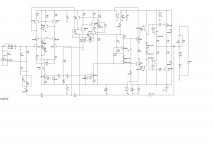
I changed a bit in a mintime and here is a new circuit diagram.
Input stage up to predriver will be powered from separate voltage higher by 5V then output valtage. Now I can use simple clamp(D4 and D5) to prevant clipping in OPS.
I apreciate commentcs before to start practical implamentation.
This one shows simulated distortion of 0.000014% at 1W and 10kHz.
dado
Attachments

Do D7 & D8 reduce the driver bias current, as the outputs warm up? Or do they increase the driver bias current?
Do D7 & D8 reduce the driver bias current, as the outputs warm up? Or do they increase the driver bias current?
I am not sure. I think that this influence is minor, but I have to simulate it, as I have not yet.
More about this diodes look at http://www.diyaudio.com/forums/soli...al-compensation-thermal-trak-transistors.html
dado
Try this (below) , . For a EF2 -only 3 diodes (4 for triple). If over compensated , try 3 diodes , adjust the 330R. I simmed with mur320's - just about equivalant to the TT's. The 3503 is NOT thermally coupled.
PS - playin' around , I ran this just to see .... as it is a MJE/NJW OP stage is biased at exactly 75ma/.22Re with what you see. The NJL(TT), might be slightly different.
OS
PS - playin' around , I ran this just to see .... as it is a MJE/NJW OP stage is biased at exactly 75ma/.22Re with what you see. The NJL(TT), might be slightly different.
OS
Attachments
Last edited:
Try this (below) , . For a EF2 -only 3 diodes (4 for triple). If over compensated , try 3 diodes , adjust the 330R. I simmed with mur320's - just about equivalant to the TT's. The 3503 is NOT thermally coupled.
PS - playin' around , I ran this just to see .... as it is a MJE/NJW OP stage is biased at exactly 75ma/.22Re with what you see. The NJL(TT), might be slightly different.
OS
Thanks OS, I tried this configuration as used in Leach amp. I bought Cordell book and after that decided to use his recommendation for bias spreader. In this case I use two TT diodes to stabilize the bias and other two to keep the impedance between drivers emitter very small. In this amp I use two TT pairs as that is more than enough for my project(amps for Orion loudspeakers).
dado
Why not to use convenience of the higher voltage for the imput part and not to use cascoded VAS.
Here is circuit diagram with Hawksford cascode for the VAS.
Simulated distortion:
.step level=0.088
Fourier components of V(vout)
DC component:-0.0109679
Harmonic Frequency Fourier Normalized Phase Normalized
Number [Hz] Component Component [degree] Phase [deg]
1 1.000e+04 2.775e+00 1.000e+00 -0.75° 0.00°
2 2.000e+04 4.674e-08 1.684e-08 131.39° 132.14°
3 3.000e+04 1.078e-07 3.884e-08 111.54° 112.29°
4 4.000e+04 6.440e-09 2.321e-09 7.71° 8.46°
5 5.000e+04 2.205e-09 7.948e-10 38.68° 39.42°
6 6.000e+04 6.127e-09 2.208e-09 -4.10° -3.35°
7 7.000e+04 6.956e-09 2.507e-09 -6.21° -5.46°
8 8.000e+04 7.828e-09 2.821e-09 -4.59° -3.84°
9 9.000e+04 8.796e-09 3.170e-09 -3.38° -2.63°
Total Harmonic Distortion: 0.000004%
.step level=0.5
Fourier components of V(vout)
DC component:-0.0109674
Harmonic Frequency Fourier Normalized Phase Normalized
Number [Hz] Component Component [degree] Phase [deg]
1 1.000e+04 1.577e+01 1.000e+00 -0.75° 0.00°
2 2.000e+04 9.157e-07 5.808e-08 53.27° 54.02°
3 3.000e+04 1.722e-06 1.092e-07 110.31° 111.06°
4 4.000e+04 8.287e-07 5.257e-08 -152.95° -152.20°
5 5.000e+04 2.511e-06 1.593e-07 141.56° 142.31°
6 6.000e+04 5.673e-07 3.598e-08 -124.60° -123.86°
7 7.000e+04 2.376e-06 1.507e-07 154.46° 155.20°
8 8.000e+04 1.740e-07 1.104e-08 -80.98° -80.23°
9 9.000e+04 1.428e-06 9.057e-08 161.87° 162.62°
Total Harmonic Distortion: 0.000028%
.step level=1.3
Fourier components of V(vout)
DC component:-0.0109574
Harmonic Frequency Fourier Normalized Phase Normalized
Number [Hz] Component Component [degree] Phase [deg]
1 1.000e+04 4.099e+01 1.000e+00 -0.75° 0.00°
2 2.000e+04 1.297e-05 3.165e-07 7.47° 8.22°
3 3.000e+04 3.698e-05 9.022e-07 110.09° 110.84°
4 4.000e+04 7.739e-06 1.888e-07 -151.51° -150.77°
5 5.000e+04 2.625e-05 6.404e-07 -42.79° -42.04°
6 6.000e+04 2.595e-06 6.332e-08 74.68° 75.43°
7 7.000e+04 1.305e-05 3.184e-07 144.61° 145.36°
8 8.000e+04 3.457e-06 8.433e-08 -140.42° -139.67°
9 9.000e+04 7.925e-07 1.933e-08 -68.20° -67.45°
Total Harmonic Distortion: 0.000121%
dado
Attachments
- Status
- Not open for further replies.
- Home
- Amplifiers
- Solid State
- ThermalTrak+TMC amp