What happens if you add an output cap to your model? I kept the output caps in mine because they are in a 'known-stable reg' circuit. If I delete them I can get things to work but only for very small Vstim levels. And I'm no longer confident the reg is then stable as it appears easy to increase Vstim and cause oscillation.
I see your Vstim is 1V amplitude but Vregout isn't 12VDC plus 1V amplitude sinus.
I see your Vstim is 1V amplitude but Vregout isn't 12VDC plus 1V amplitude sinus.
I think you might have forgotten that Walt's 350 ohm pulldown resistor, is intended to drive a 1 volt 200 kHz sinewave into 100 nanofarads. dv/dt = (2*pi*f*Amplitude) = 1.25E6 volts per second. Icap = C*dv/dt = 125 mA.
If you really want to drive (2 x 470uF) then you'll need one thousand two hundred amperes flowing in the pulldown resistor.
The circuit in post #342 has a gain of (R4+R5)/R5 = 1.74. Unlike Walt's inverting amplifier, this is a noninverting amplifier. That's why the crests are at 13.7 volts (12 + (1.0*1.74)) and the troughs are at 10.3 volts (12 - (1.0*1.74)) .
Ok point taken regarding output caps but I'm getting confused by your comment regarding the pull-down resistor. I understood the 350 ohm resistor's purpose was merely to establish a quiescent current in the rail driver (18V/350R = 51mA) and that its load is determined by the input impedance of the reg DUT and the DUT's load. We want to measure the DUT at, say, 1A of current load and so (with 12V reg Vout) we will attach a 12R load to its output terminals (load will slightly exceed 1A). The rail driver has to provide the 1A DC current plus the current required to drive the DUT's input cap at freq X (200kHz in the case of Walt) plus any quiescent losses. I don't follow the relationship between the pull-down resistor and 1V 200kHz sine wave into 100n.
It seems resistor R1 is critical to this rail driver's stability. Neither of the MOSFET-based boards I have made have provision for such resistor between the op amp output and the level shifter (a resistor in the gatestopper position doesn't help) so it may require a bit more hacking. I'll have a look. (Walt needed to trim the equivalent of your R5. It doesn't seem necessary here though which is good as that would require some hacking also.)
It seems resistor R1 is critical to this rail driver's stability. Neither of the MOSFET-based boards I have made have provision for such resistor between the op amp output and the level shifter (a resistor in the gatestopper position doesn't help) so it may require a bit more hacking. I'll have a look. (Walt needed to trim the equivalent of your R5. It doesn't seem necessary here though which is good as that would require some hacking also.)
If you drive a "C" farad capacitor with an "f" hertz sinewave whose amplitude is "A" volts, the capacitor voltage is V(t) = A*sin(2*pi*f*t) and the capacitor current is I(t) = C*dV/dt. Carrying out the derivative, I(t) = C*A*(2*pi*f)*cos(2*pi*f*t).
The peak current occurs where cosine(...) equals 1.0, thus Ipeak = C*A*(2*pi*f)*1
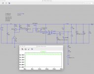
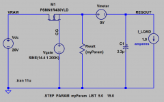
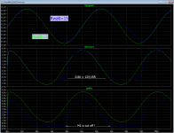
To illustrate the problems of driving capacitors larger than Walt Jung's 0.1 microfarads, I put together a stripped down simulation using C = 2.2 microfarads; see Figure 1.
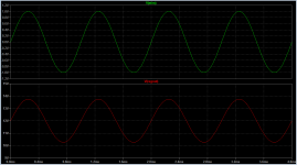
The formula above says the capacitor current's Ipeak = (2.2uF)*(1.0V)*(2*pi*2E5) = 2.76 amps. At the crest of the 200kHz cosine wave current, the MOSFET must supply 2.76 amps to charge the cap, plus another 1.00 amps to drive the load, plus (12V/Rwalt) into the pulldown resistor. For Rwalt=5.0R that adds up to 6.16 amps. Presto, the bottom panel of Figure 2 shows that the green curve peaks at 6.16 amperes. Science works.
However the MOSFET can only pull the capacitor voltage up; it can't pull the capacitor voltage down. Pulling down the capacitor we have Rwalt and I_LOAD working in parallel. The peak pulldown current discharging the capacitor is 2.76 amps; 1.0 amps of that comes from I_LOAD and 1.76 amps comes from Rwalt. Thus we require Rwalt <= (12/1.76); namely, Rwalt <= 6.82 ohms.
I simulated the circuit with two choices of Rwalt. One of them was less than 6.82 ohms (namely: 5.0 ohms, green trace), and the other was greater than 6.82 ohms (namely: 15 ohms, blue trace). The blue trace shows what happens when Rwalt is too large to sink the required 1.76 amps from the capacitor. The slew rate dV/dt is too slow to track a 200 kHz sinewave {top panel}, the current delivered to (Cap + Load) doesn't make it all the way down to -1.76 amperes {middle panel}, and the MOSFET completely cuts off so the control system is is totally nonfunctional {bottom panel}. No es bueno.
All of the foregoing illustrates Walt's point: don't try to drive big capacitances from your raildriver!! Not 2.2uF and certainly not (2 x 470uF). A resistor pulldown raildriver that can push 200kHz @ 1.0V into 2.2uF, squirts truly enormous currents through its series pass device (6.16 amps), and dissipates enormous power in its resistor (21.1 watts). At the very least you'll want a class-AB power amplifier with GBW>10MHz, and a push pull output stage on a big heatsink, if you intend to drive 2.2uF. If you intend to drive (2 x 470uF), heaven help you.
The peak current occurs where cosine(...) equals 1.0, thus Ipeak = C*A*(2*pi*f)*1
To illustrate the problems of driving capacitors larger than Walt Jung's 0.1 microfarads, I put together a stripped down simulation using C = 2.2 microfarads; see Figure 1.
The formula above says the capacitor current's Ipeak = (2.2uF)*(1.0V)*(2*pi*2E5) = 2.76 amps. At the crest of the 200kHz cosine wave current, the MOSFET must supply 2.76 amps to charge the cap, plus another 1.00 amps to drive the load, plus (12V/Rwalt) into the pulldown resistor. For Rwalt=5.0R that adds up to 6.16 amps. Presto, the bottom panel of Figure 2 shows that the green curve peaks at 6.16 amperes. Science works.
However the MOSFET can only pull the capacitor voltage up; it can't pull the capacitor voltage down. Pulling down the capacitor we have Rwalt and I_LOAD working in parallel. The peak pulldown current discharging the capacitor is 2.76 amps; 1.0 amps of that comes from I_LOAD and 1.76 amps comes from Rwalt. Thus we require Rwalt <= (12/1.76); namely, Rwalt <= 6.82 ohms.
I simulated the circuit with two choices of Rwalt. One of them was less than 6.82 ohms (namely: 5.0 ohms, green trace), and the other was greater than 6.82 ohms (namely: 15 ohms, blue trace). The blue trace shows what happens when Rwalt is too large to sink the required 1.76 amps from the capacitor. The slew rate dV/dt is too slow to track a 200 kHz sinewave {top panel}, the current delivered to (Cap + Load) doesn't make it all the way down to -1.76 amperes {middle panel}, and the MOSFET completely cuts off so the control system is is totally nonfunctional {bottom panel}. No es bueno.
All of the foregoing illustrates Walt's point: don't try to drive big capacitances from your raildriver!! Not 2.2uF and certainly not (2 x 470uF). A resistor pulldown raildriver that can push 200kHz @ 1.0V into 2.2uF, squirts truly enormous currents through its series pass device (6.16 amps), and dissipates enormous power in its resistor (21.1 watts). At the very least you'll want a class-AB power amplifier with GBW>10MHz, and a push pull output stage on a big heatsink, if you intend to drive 2.2uF. If you intend to drive (2 x 470uF), heaven help you.
Attachments
However the MOSFET can only pull the capacitor voltage up; it can't pull the capacitor voltage down.
Thanks. This bit (in particular) is what I missed.
So solve for Cin at a load which is a fair test of the regulator and at which Rwalt's power dissipation is sensible or Iload provides the necessary current to pull down the cap at design freq X. For example, at Iload = 0.5A and a maximum test frequency of 100kHz (significant headroom above what I could test at) Cin could be almost as high as 800nF without the need for Rwalt. An added Rwalt could just provide headroom. (And 750nF might well be easier to find.)
Walt says he sized his raildriver circuitry to drive 0.1uF because IC voltage regulator datasheets (that he was reading in 1994-1995) require at least 0.1uF at their Vin pin.
Indeed. And presumably he decided to use Rwalt (18.5V/350R => 53mA) in case Iload was insufficient on its own to pull the capacitor voltage down quickly enough at 200kHz. He was driving 1Vpp, 0.5V amplitude. Using the formula you posted above the peak current needed to pull down the voltage of such cap at 200kHz is (0.1uF)*(0.5)*(2*Pi*2E5) = at least 63mA.
I can't measure to 200kHz. Even 100kHz is very likely a stretch. I also have a regulator which I ought to test at, presumably, at least 0.5A. These would seem to be advantages. But I have a pre-regulator which would prefer 470nF ahead of it instead of 100nF. If I use 470nF and limit things to 100kHz, and again 0.5V amplitude, I need Iload + I(Rwalt) to total more than 148mA. 0.5A Iload would seem to cover it and hence Rwalt is unnecessary. (For the Iload was thinking of three 8 ohm - or four 6 ohm - 3W or 5W resistors in series.) Maybe I am missing something.
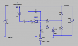
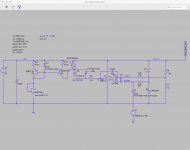
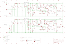
I can hack a spare reg board to construct the circuit attached. It models stable. I had to cut tracks to provide for R5 and R6 but all else would seem relatively simple although perhaps my attachment of V1 may be a little crude. (I have a BNC to crocodile clips lead for my waveform generator.) Perhaps it will suffice for a novice look.
I can't measure to 200kHz. Even 100kHz is very likely a stretch. I also have a regulator which I ought to test at, presumably, at least 0.5A. These would seem to be advantages. But I have a pre-regulator which would prefer 470nF ahead of it instead of 100nF. If I use 470nF and limit things to 100kHz, and again 0.5V amplitude, I need Iload + I(Rwalt) to total more than 148mA. 0.5A Iload would seem to cover it and hence Rwalt is unnecessary. (For the Iload was thinking of three 8 ohm - or four 6 ohm - 3W or 5W resistors in series.) Maybe I am missing something.
I can hack a spare reg board to construct the circuit attached. It models stable. I had to cut tracks to provide for R5 and R6 but all else would seem relatively simple although perhaps my attachment of V1 may be a little crude. (I have a BNC to crocodile clips lead for my waveform generator.) Perhaps it will suffice for a novice look.
Attachments
Last edited:
Seems like a good experiment. It will either succeed in measuring line rejection, or show you one or more places where the test setup needs improvement.
If the circuit is stable it's good. Seems like you could get by with just R3 or R6 and not need both but if it's stable it's good. In your situation I think I'd order several Ccomp values just as cheap insurance against unexpected misbehavior not seen in simulation. Like maybe 15pF, 20pF, 33pF, 50pF, 100pF. Now if you need them you don't have to wait a shipping delay to get them, and if you don't need them you're not out a bunch of money.
I'd suggest extreme conservatism when selecting the wattage of load resistors, at least 2X and preferably 3X the actual dissipation. So if you're going for 18V across 24R that's 13.5W actual, and I recommend at least 30W rating. So six 5W resistors. Them babies get HOT!
BTW I purchased an inexpensive electronic load (2 channel programmable current sink with enormous cooling fans) from eBay, the KL283, to test my RingNot power supply. It comfortably handled 4.0A at +28V and another 4.0A at -28V. It worked very well and I am glad I bought it.
In sim R6 was necessary i.e. R3 wasn't effective. R3 may not be needed (in sim it wasn't needed for stability). R6 wasn't in the reg circuit and so I had to cut a placeholder for it
Agreed re Ccomp.
Sorry regarding load resistors I meant those attached to the output of the regulator under test. So they're across 12v. I was thinking this load enough to not need "Rwalt".
I can see how that device could come in handy.
Agreed re Ccomp.
Sorry regarding load resistors I meant those attached to the output of the regulator under test. So they're across 12v. I was thinking this load enough to not need "Rwalt".
I can see how that device could come in handy.
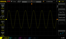
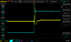
Hmmm. I haven't had any time to think about this result yet - only a very brief period to do the test - but this clearly isn't right. The DC level is about 18V but the riding stimulus isn't correct. It's meant to be 0.5Vpp (less than what will be used) 1kHz, zero DC offset. This is just the rail driver - no regulator DUT attached, no load (except its own quiescent, c70mA).
Attachments
I found the first problem. I was worried about exceeding at startup the max Vgs rating of the pass MOSFET: +-20V. Without thinking too much I placed a 20V zener to ground at the gate. An 18V protection zener had been used for the 12V reg but of course with an 18V +- 0.5V that doesn't work. The gate needs to drive to c21.7V or more. I need to protect Vgs a different way.
Last edited:
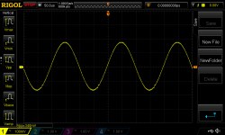
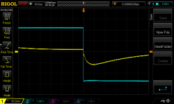
The Vref waveform seems ok (albeit there is a "disturbance" at the lower part of the waveform as the voltage turns upwards). Pic 1.
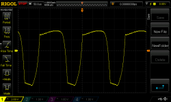
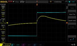
The key issue is output from the op amp. Sim suggests an expected swing of just 0.9Vpp with 0.34Vpp as the stimulus: 2.6 x 0.34 = 0.9V. But I am getting a massive c10V swing when I probe OAout (pic 2). Presumably it is asymmetric because with 18.1V output and a supply to the OA from this output the OA output hits its V+ rail (adjusted for the DC level shift of 5V and the amount to which the AD817 can approach its supply rail).
I think the problem might be I am asking the op amp to drive the cap bypassing the DC level shift with 0.9Vpp sinus. This cap is currently 180uF. Sim suggests the current is a low 8mA or so but I presume this is just the DC current the OA has to sink from the current source/mirror. If I am right then this cap would have to be tiny for an AD817 to be able to drive it 1Vpp at 100kHz... It means I have to yank out the level shift and cap and supply the OA and Vref from 24Vin from my bench PSU.
Attachments
Last edited:
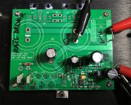
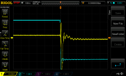
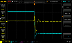
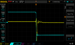
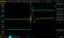
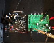
Transient testing with chop chop box and new LM2941 output cap C9: ESC477M035AH4AA 470uF, 35V, 0.039 ohms ESR, 1.04 amps ripple current.
Pass transistor Q7: 2SC6144SG
Driver transistor Q9: MMBTH10
ESR resistor R15: 0.1R
R25 and R44 are still 0R
First 5 pics probing the regulator output. Last three probing the pins of the new LM2941 output cap.
One might be forgiven for thinking the results are worse than those in post 312 and 326?
Pass transistor Q7: 2SC6144SG
Driver transistor Q9: MMBTH10
ESR resistor R15: 0.1R
R25 and R44 are still 0R
First 5 pics probing the regulator output. Last three probing the pins of the new LM2941 output cap.
One might be forgiven for thinking the results are worse than those in post 312 and 326?
Attachments
-
 NewFile77.png34.6 KB · Views: 95
 -
 NewFile83.png32.8 KB · Views: 79
 -
 NewFile82.png32.6 KB · Views: 79
 -
 NewFile81.png37.3 KB · Views: 75
 -
 NewFile84.png34.8 KB · Views: 70
 -
 NewFile80.png35.1 KB · Views: 84
 -
 NewFile79.png33.9 KB · Views: 79
 -
 NewFile78.png36.2 KB · Views: 81
 -
 Darl Circuit.png96.8 KB · Views: 99
Last edited:
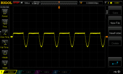
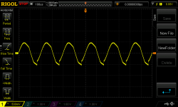
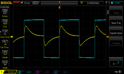
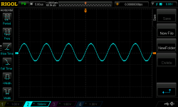
PSRR intermediary setup test. Rail driver attached to reg DUT. I attached two 10W 12R resistors in series to the reg DUT output. I slowly dialled up the stimulus frequency to 100kHz. The reg heatsink got much hotter than I expected (49.4C versus an ambient of 21.7C ***) but there wasn't any smoke anywhere! My bench PSU registered a total current draw of 0.64A. I attached my scope to the output of the rail driver. Pic of 100kHz output attached - just 300mVpp stimulus in this test. My only concern is that the waveform seems to have higher peaks than troughs. There seems to be an offset of about 20-40mV. The scope FFT (as best as I can use it) would suggest the waveform is relatively clean, however.
*** the Aavid 529802B02500G heatsink is meant to be 3.7C/W. I have attached a load of 0.5A and the heatsink supports both the LM2941 and the pass transistor. Vin is about 18V and Vout 12V and so I was expecting a temp of circa 21.7 + 0.5*6*3.7 = 33C. Even assuming all 0.64A is across the heatsink the rise in temperature is more consistent with a coefficient of 7.2C/W. It would seem that to achieve a thermal resistance of 3.7C/W there needs to be considerable air movement. A full amp load would leave the heatsink really rather hot.
*** the Aavid 529802B02500G heatsink is meant to be 3.7C/W. I have attached a load of 0.5A and the heatsink supports both the LM2941 and the pass transistor. Vin is about 18V and Vout 12V and so I was expecting a temp of circa 21.7 + 0.5*6*3.7 = 33C. Even assuming all 0.64A is across the heatsink the rise in temperature is more consistent with a coefficient of 7.2C/W. It would seem that to achieve a thermal resistance of 3.7C/W there needs to be considerable air movement. A full amp load would leave the heatsink really rather hot.
Attachments
- Status
- Not open for further replies.
- Home
- Amplifiers
- Power Supplies
- Thermal considerations for Fairchild SDIP bridge rectifiers