Nice project Gnu! Like it alot.
I was just wondering from where you bought that aluminium, and how much did you pay?
I need to build a casing for my GC and want to make it in alu.
Mvh Carl-Johan...
I was just wondering from where you bought that aluminium, and how much did you pay?
I need to build a casing for my GC and want to make it in alu.
Mvh Carl-Johan...
einthoven said:The reflector is really a problem... Those glass reflectors from daylight projectors actually are too small for those big lamps we use. But DIY reflectors (aluminium, steel etc.) reflect too much InfraRed to the lcd an fresnels ... they melt.
That's really a problem that still has to be solved
My personaly idea was a transparent, temperature resistant, round glass (from the supermarket or else) to be sprayed with car aluminium spray as reflector. I wonder if it would reflect less IR. Need time to try if it works ..
Do you have the glass refl. from www.exclusiv-online.com?
Any plans to 'dremel' it for a better fit of the lamp?
yeah there is definately some improvements needed to the types of reflectors most of us use today, as there is a lot of light from the bulbs escaping out on the sides and it feels like such a waste of image brightness. Imagine if 90% of the light could be reflected on to the screen....
Do you know if a IR-filter will stop the IR's when using a diy reflector?
Yes I use the reflector from exclusiv-online.com
elstcb said:Woah that is truely awesome work, good luck with the rest of it, I'll be checking back on a regular basis!
Thx a lot, make shure you you do because next update will hopefully be a large one (and the last) with the finishing and result pics. I am curently painting the internals black and fabricating the top lid. Then there is only some ataching and wiering left to do.
CJ900RR said:Nice project Gnu! Like it alot.
I was just wondering from where you bought that aluminium, and how much did you pay?
I need to build a casing for my GC and want to make it in alu.
Mvh Carl-Johan...
Hej ... and thx
I bought the alu at my local "metalworkshop??" (plåtverkstad) for ~60$ (400sek)
The aluminium is 1,50 mm thick and 2x1 was the smallest size they could order for me. They can probably cut it for you too into exact dimentions but i didn't have the dimentions at that time so I took the whole thing with me home 😛 I live in a small town and it was only a small metalshop that nomaly make roofs and ventilations, so im shure you have something similar around Alingsås.
hi
an IR-filter will help.
Many diy forum users build own reflectors and it works - but only if they use many fans to blow the hot air out. The projectors are loud and a lot of light comes out of the blow-holes.
Another problem is that those ir-filters stop working if the temperature gets too high. So you have to use more fans.
And condensor lenses often break with diy reflectors because they don't like it too hot.
Some people use surface mirrors to reflect the light to the LCD.
Surface mirrors only reflect 'cold' light, ir will not be reflected.
Perhaps this could help...
Seems very difficult to solve....
90% of the light ... mhm, but then another problem will appear - the black of your image becomes light grey.
And the reflector is not the only cause for the loss of light....
those lcds (hami etc) are not made to work in a projector - so they steal perhaps 30 % of the light.
The lenses are not optimal and more light gets lost.
I think it would be very expensive to optimize the DIY Pj's ... too expensive to be profitable - in view of the prices of low level projectors from BenQ etc (about 600 €)
bye
hi... okay thx for the useful info.
When I wrote 90% I kind of ment that it would be great to reflect almost al of the ligt onto the TFT screen. I know there is a lot of light getting lost on the way. Collecting as much of the light as possible doesent mean the black of the screen turns grey, only that we donsn't need to use as strong lamps as we do today.
take care
/gnu
Okay.. time for a new update. Been a while since the last one but I don't have much time to work on this project at the moment as I have moved to a new town to sudy. But on the weekends I usually take a trip home to work on it, and this is the work so far. I took some more pictures this week but I forgot the memorystick with all the pics :wallbash:. But I guess this will be enough for so long.
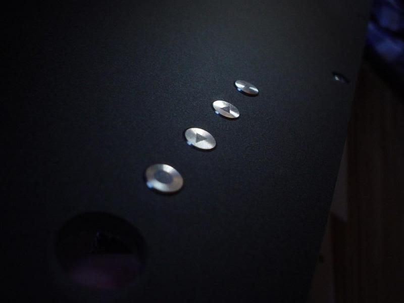
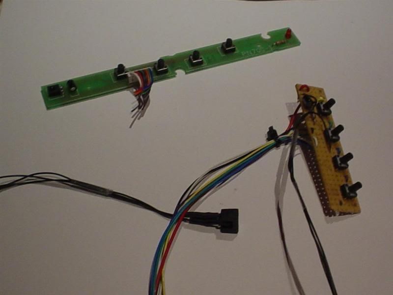
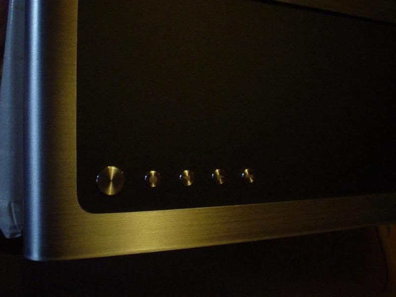
This is how the buttons turned out. The power button has not been mounted on the picture yet, but it is fabricated. The original "power" (1/0) symbol was to hard to do. I tried different symbols but the non of them loocked any good. So the power button will be totaly clean without any symbol. Also the "menu" symbol was changed to a ( - ) sign.
(tft power / left / right / menu)

(CLICK TO ZOOM)
Blury shoot but you get a felleing of how the symbols look

(CLICK TO ZOOM)
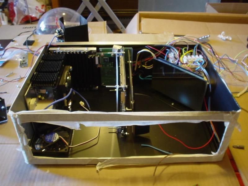
The whole projector is dissasembled because it needs to be painted black.
You might wonder why I didn't do that at the early beginning..well I started this project almost 2 years ago and didn't want to start messing with the paint until all parts were fabricated.

(CLICK TO ZOOM)
the side mounted L-profiles that will help support the whole case structure

(CLICK TO ZOOM)

(CLICK TO ZOOM)
Excuse the huge amount of masking tape...but the front is somewhere underneath. I promisse 🙂

(CLICK TO ZOOM)

(CLICK TO ZOOM)

(CLICK TO ZOOM)

(CLICK TO ZOOM)

(CLICK TO ZOOM)
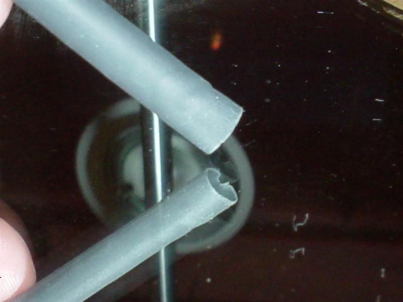
This is the front surface mirror. If you don't know what a front surface mirror is. Take a look at the pictures below.

(CLICK TO ZOOM)
This is a normal mirror, it has the reflecting mirror surface on the backside of the glass. This creates multiple "ghost" images because the light also reflects on the surface of the glass.

(CLICK TO ZOOM)
The front surface mirror have the reflecting surface on the front an therefore there is no glass infront to reflect "ghost" images. This is the same type of mirror that's used in OH-projectors. Fron surface mirrors are also very sensitive for scrathes...I tried to clean mine with one of those ultra soft cleaning towels for glasses. But even that created very small scrathes.

(CLICK TO ZOOM)
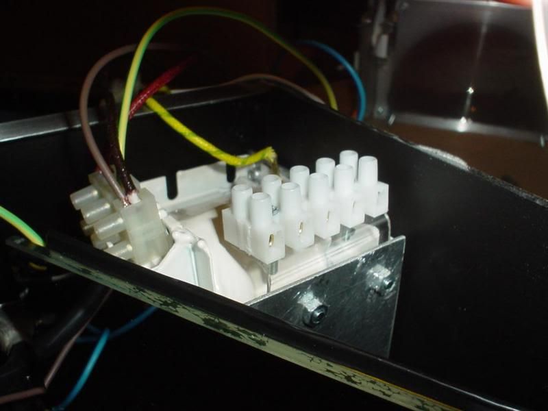
Time to create some order in the Lamp ballast cabling

(CLICK TO ZOOM)
The smaller white square thingy behind the mirror is the ignitor for the lamp

(CLICK TO ZOOM)
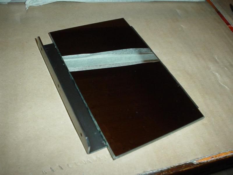
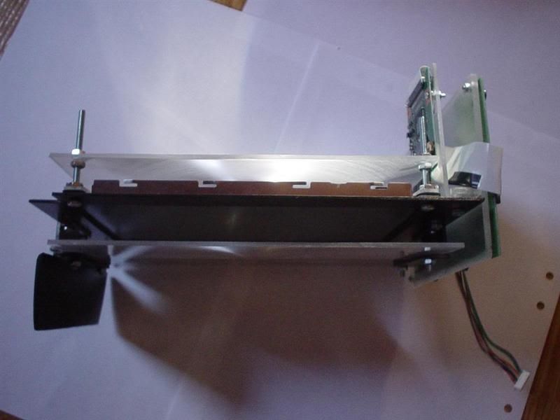
TFT holder is painted black. And Fresnel lenses installed. The black thing to the left will act as an airblock to prevent the air from the fan to escape away from the TFT display.

(CLICK TO ZOOM)
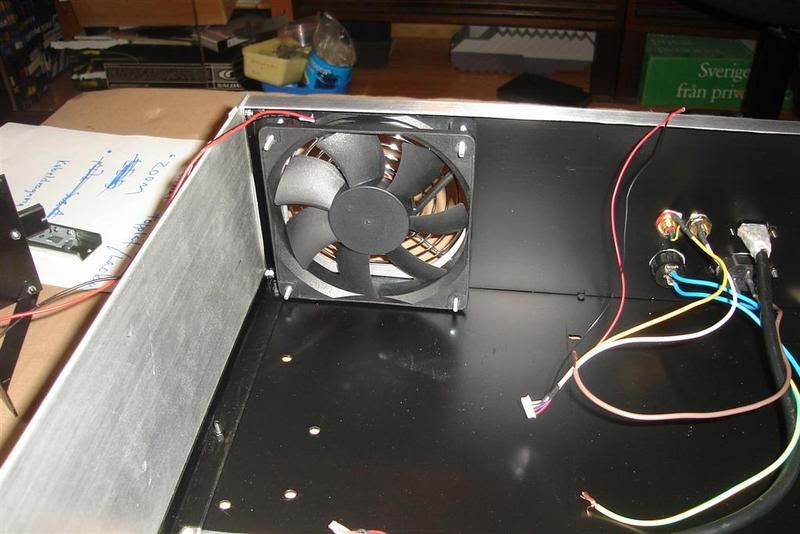
TFT and 80mm lamp fan added

(CLICK TO ZOOM)
/GNU
This is how the buttons turned out. The power button has not been mounted on the picture yet, but it is fabricated. The original "power" (1/0) symbol was to hard to do. I tried different symbols but the non of them loocked any good. So the power button will be totaly clean without any symbol. Also the "menu" symbol was changed to a ( - ) sign.
(tft power / left / right / menu)
(CLICK TO ZOOM)
Blury shoot but you get a felleing of how the symbols look
(CLICK TO ZOOM)
The whole projector is dissasembled because it needs to be painted black.
You might wonder why I didn't do that at the early beginning..well I started this project almost 2 years ago and didn't want to start messing with the paint until all parts were fabricated.
(CLICK TO ZOOM)
the side mounted L-profiles that will help support the whole case structure

(CLICK TO ZOOM)

(CLICK TO ZOOM)
Excuse the huge amount of masking tape...but the front is somewhere underneath. I promisse 🙂
(CLICK TO ZOOM)
(CLICK TO ZOOM)

(CLICK TO ZOOM)
(CLICK TO ZOOM)

(CLICK TO ZOOM)
This is the front surface mirror. If you don't know what a front surface mirror is. Take a look at the pictures below.
(CLICK TO ZOOM)
This is a normal mirror, it has the reflecting mirror surface on the backside of the glass. This creates multiple "ghost" images because the light also reflects on the surface of the glass.
(CLICK TO ZOOM)
The front surface mirror have the reflecting surface on the front an therefore there is no glass infront to reflect "ghost" images. This is the same type of mirror that's used in OH-projectors. Fron surface mirrors are also very sensitive for scrathes...I tried to clean mine with one of those ultra soft cleaning towels for glasses. But even that created very small scrathes.

(CLICK TO ZOOM)
Time to create some order in the Lamp ballast cabling
(CLICK TO ZOOM)
The smaller white square thingy behind the mirror is the ignitor for the lamp

(CLICK TO ZOOM)
TFT holder is painted black. And Fresnel lenses installed. The black thing to the left will act as an airblock to prevent the air from the fan to escape away from the TFT display.
(CLICK TO ZOOM)
TFT and 80mm lamp fan added
(CLICK TO ZOOM)
/GNU
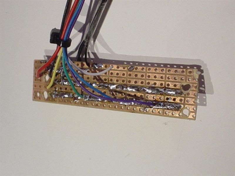
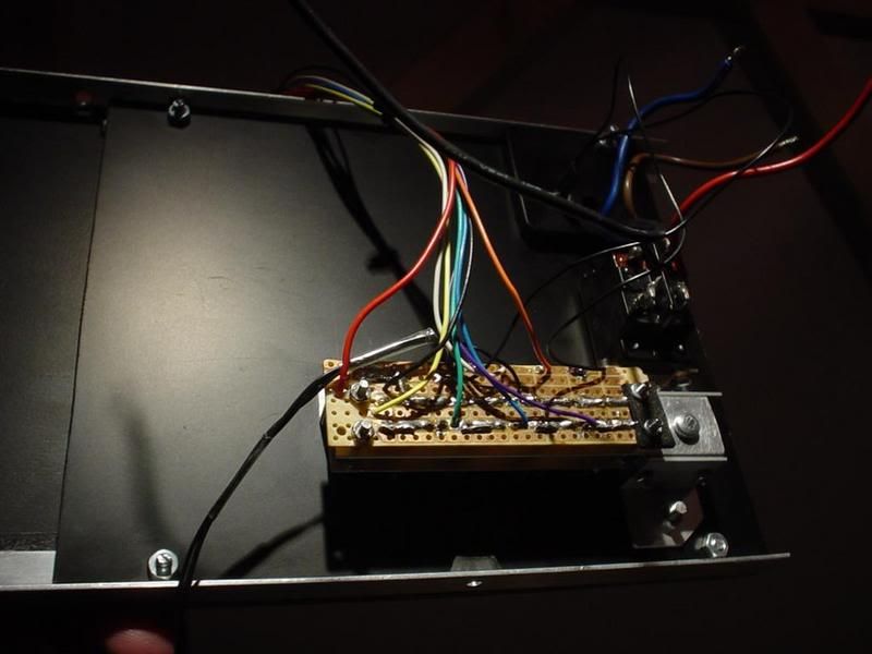
The button electronics needed a makower to fit my design. I don't think I need to say witch one is the "new". The black little thing in the middle is the IR-sensor with holder.

(CLICK TO ZOOM)
my soldering pen isn't the best, but atleast it works.

(CLICK TO ZOOM)
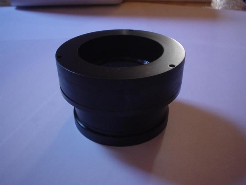
The triplet lens spacers are painted black on the inside and top to prevent light from escaping. It looks like they are made out of black plastic. If I hade painted them black on the ouside the paint would probably have pealed of when zooming because its a very tight fit against the hole in the front.

(CLICK TO ZOOM)
Thats it for today. Will make a trip home this weekend to finish the projector. And will probably have some result pics and videos next week. If everything works as it is suposed to...I seriously hope I havent damaged the TFT or any other expensive stuff without knowing it.
Well will see.
/GNU
(CLICK TO ZOOM)
my soldering pen isn't the best, but atleast it works.
(CLICK TO ZOOM)
The triplet lens spacers are painted black on the inside and top to prevent light from escaping. It looks like they are made out of black plastic. If I hade painted them black on the ouside the paint would probably have pealed of when zooming because its a very tight fit against the hole in the front.
(CLICK TO ZOOM)
Thats it for today. Will make a trip home this weekend to finish the projector. And will probably have some result pics and videos next week. If everything works as it is suposed to...I seriously hope I havent damaged the TFT or any other expensive stuff without knowing it.
Well will see.
/GNU
Awesome work as usual! I look forward to more pix. Have you done any testing of the lCD panel and projected image yet?
good god..... It sure puts a shame to my woodworking "skills" 
just wondering though, how many bits have you gone through? haha
just wondering though, how many bits have you gone through? haha
cookie said:Awesome work as usual! I look forward to more pix. Have you done any testing of the lCD panel and projected image yet?
hi.. yeah I made some testing a while back ago to make shure it all worked well. I took a few blury shoots but nothing to fancy to show as the lenses and mirror wasn't tuned. Will wait for the resultpics until the whole procet is done. And that will be very soon.
escalade182 hehe maybe try working with alu, actualy I think its easier to get great results with alu than with wood.
how many bits have you gone through? hm... do you mean how many drillbits I have broken or how many parts I have used?.....there is alot of both actually😀
/GNU
yeah I was talking about drill bits. I had a sheet of aluminum once apon a time but the bit went dull after 10 holes. the drill press I recently purchased makes it A LOT easier, wow. probably the best tool i have ever purchased...I should give it another go. you inspired me to want to build something... I have to finish the project I'm on though. (all oak - bar table) it's been a pain in the *** so far but mostly because I'm going for that high-end look, like your projector. if the wood splinters...I start over. its frustrating, but I love it.
Thx for the nice comment cromaclear-crt
..since you cant wait..heres a mini update for ya..
I have been working on finishing the projector this weekend. Been working all days long only stopping for food and sleep. Today I was actually running back and forth between the projector and the workshop with parts, because me and the projector had a train to catch. I was afraid it wouldnt make the trip in one piece but it looks like it maid it. Will fire it upp tomorrow and post the finishing pics.
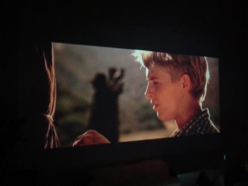
But to be honest I have already tested it, I just had to try it out yesterday once all the wiering was done. And I actually got a cap of it.....
Here it is, a quick little TEASER 😀
/GNU

(CLICK TO ZOOM)
..since you cant wait..heres a mini update for ya..
I have been working on finishing the projector this weekend. Been working all days long only stopping for food and sleep. Today I was actually running back and forth between the projector and the workshop with parts, because me and the projector had a train to catch. I was afraid it wouldnt make the trip in one piece but it looks like it maid it. Will fire it upp tomorrow and post the finishing pics.
But to be honest I have already tested it, I just had to try it out yesterday once all the wiering was done. And I actually got a cap of it.....
Here it is, a quick little TEASER 😀
/GNU
(CLICK TO ZOOM)
The_gnu
It's clear all your great work.. looking like it's paying off big time !!
Love to see some more pics ...
It's clear all your great work.. looking like it's paying off big time !!
Love to see some more pics ...
Here are some more pictures...and one step further.
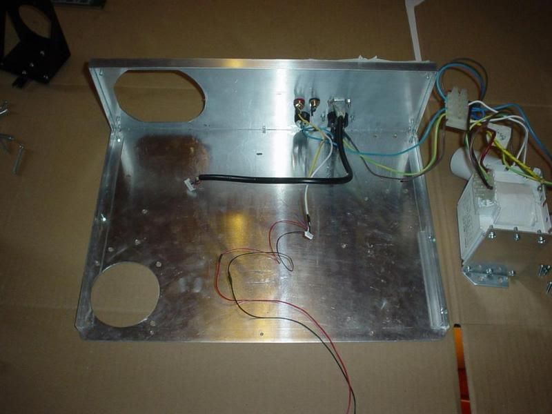
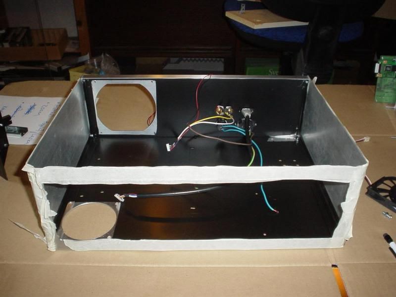
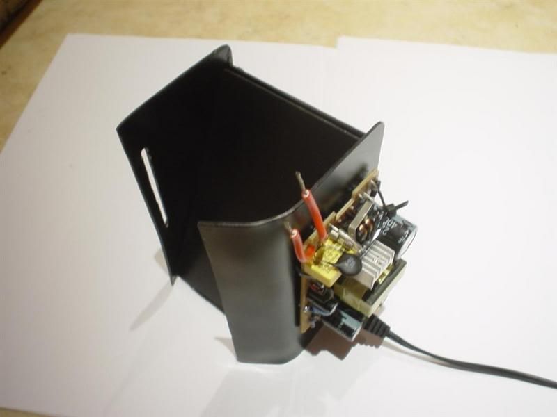
This is the "airhole" for the fan that will cool the TFT display. The electronics on the side is the 240v-->12v converter, to power the TFT and the fans.

(CLICK TO ZOOM)
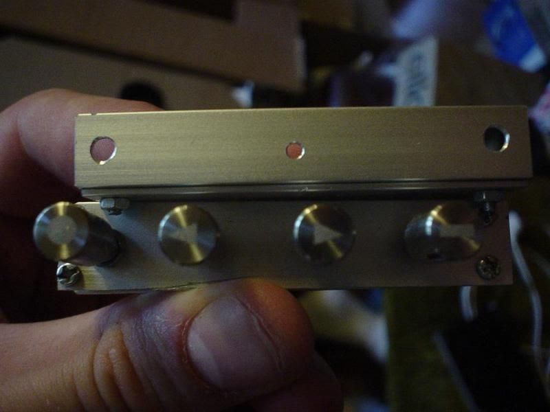
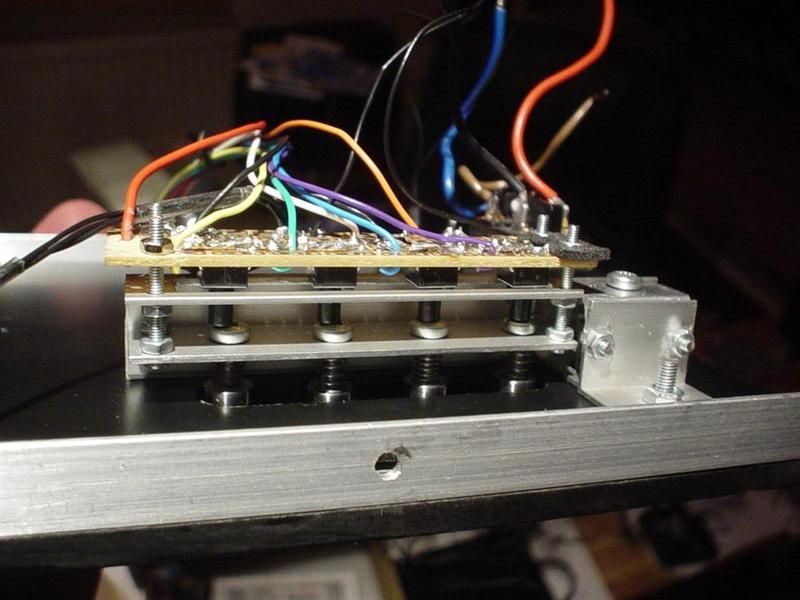
Kind of hard to see but this is the mechanism for the front mainpower switch. Mounting it as it is suposed to (in horizontal position) would have been impossible because it was blocking the bottom fan. So I hade to create this little "angle". Forgot to take pics before putting it all together but when you push the button(the larger cylinder) the original switch is forced upwards (to the right in pic) and it turns on/off.

(CLICK TO ZOOM)

(CLICK TO ZOOM)

(CLICK TO ZOOM)
Bit of dark pic of the buttons. That larger button is the mainpower (pic #2) for TFT and LAMP. It turns on the lamp and tft at the same time.

(CLICK TO ZOOM)
Triplet lens is mounted.

(CLICK TO ZOOM)
Wee look at that cable mess...I checked all the cables 5 times to make shure i didn't mix them up. And with that cable mess it was really needed.
The triplet lens holder is painted matt black as the rest of the inside of the case. Its to minimize light other than from the tft to escape, because it will affect the projected image. and YES that's toilet paper....just incase there is an accident.

(CLICK TO ZOOM)
Time to fire it up..Hope I got the wiering right.
IT WORKS!!... First time ever I have been so happy to get a blue screen. It shows that the tft and all the wiering works. The blu led is lit when the whole projector is switched on, the red one is lit as long as there is a power cable connected and the main power switch on the back is turned on. They are not as bright as in the pics, and they are stealthed to not be vissible when they are turned off.

(CLICK TO ZOOM)
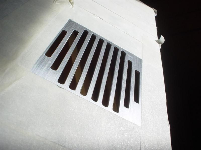
Here is the finished fan hole on the topplate... I think I spent 6-7 hours creating this one, because I wante it perfect. First i drilled holes in a row and then use my dremel to cut most of it... then i used a file and sandpaper to finish it of.

(CLICK TO ZOOM)
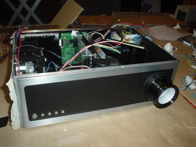
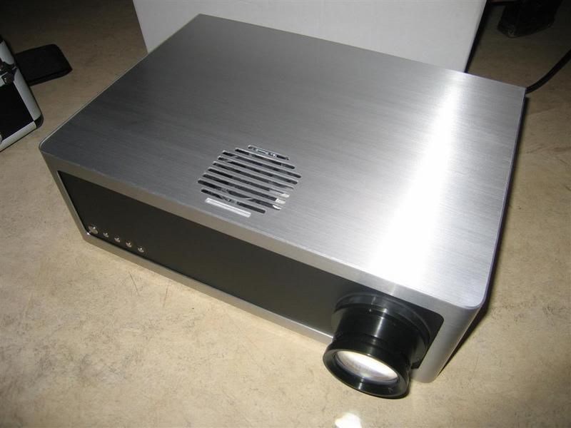
The topplate in place. and it fits perfect.., never expected that to happen.
There will be 4 "modded" mounting screws on top to hold it in place too. ..one in each corner.

(CLICK TO ZOOM)
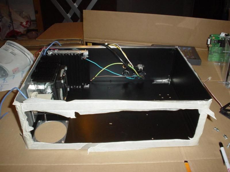
The internals at the moment. Most cables sorted out..but there is a little bit more tidying up to do. Btw the heatsink on the light box is removed temporarly...it created a little mis fit with the lid.

(CLICK TO ZOOM)
/GNU
This is the "airhole" for the fan that will cool the TFT display. The electronics on the side is the 240v-->12v converter, to power the TFT and the fans.
(CLICK TO ZOOM)
Kind of hard to see but this is the mechanism for the front mainpower switch. Mounting it as it is suposed to (in horizontal position) would have been impossible because it was blocking the bottom fan. So I hade to create this little "angle". Forgot to take pics before putting it all together but when you push the button(the larger cylinder) the original switch is forced upwards (to the right in pic) and it turns on/off.

(CLICK TO ZOOM)
(CLICK TO ZOOM)
(CLICK TO ZOOM)
Bit of dark pic of the buttons. That larger button is the mainpower (pic #2) for TFT and LAMP. It turns on the lamp and tft at the same time.
(CLICK TO ZOOM)
Triplet lens is mounted.
(CLICK TO ZOOM)
Wee look at that cable mess...I checked all the cables 5 times to make shure i didn't mix them up. And with that cable mess it was really needed.
The triplet lens holder is painted matt black as the rest of the inside of the case. Its to minimize light other than from the tft to escape, because it will affect the projected image. and YES that's toilet paper....just incase there is an accident.

(CLICK TO ZOOM)
Time to fire it up..Hope I got the wiering right.
IT WORKS!!... First time ever I have been so happy to get a blue screen. It shows that the tft and all the wiering works. The blu led is lit when the whole projector is switched on, the red one is lit as long as there is a power cable connected and the main power switch on the back is turned on. They are not as bright as in the pics, and they are stealthed to not be vissible when they are turned off.

(CLICK TO ZOOM)
Here is the finished fan hole on the topplate... I think I spent 6-7 hours creating this one, because I wante it perfect. First i drilled holes in a row and then use my dremel to cut most of it... then i used a file and sandpaper to finish it of.
(CLICK TO ZOOM)
The topplate in place. and it fits perfect.., never expected that to happen.
There will be 4 "modded" mounting screws on top to hold it in place too. ..one in each corner.
(CLICK TO ZOOM)
The internals at the moment. Most cables sorted out..but there is a little bit more tidying up to do. Btw the heatsink on the light box is removed temporarly...it created a little mis fit with the lid.

(CLICK TO ZOOM)
/GNU
Thats pretty good 🙂
Wish I could do stuff like that, just I rush things 🙁
Well done, cant wait for some more result shots
Wish I could do stuff like that, just I rush things 🙁
Well done, cant wait for some more result shots
FINALY.. I have got some result pics to show.
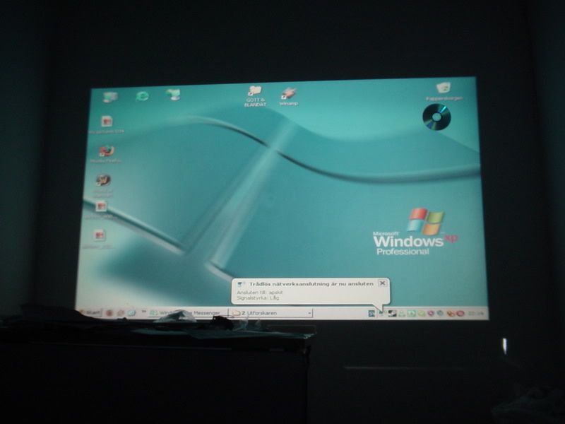
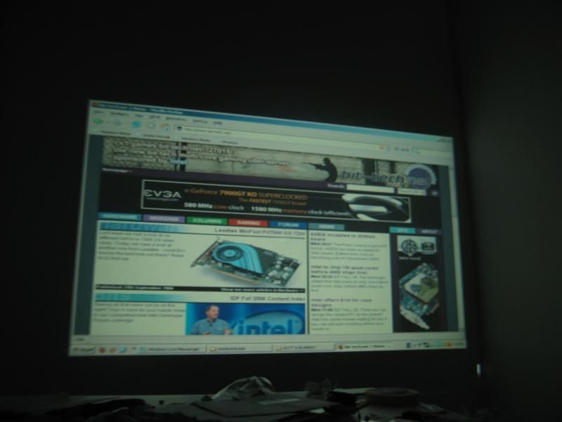
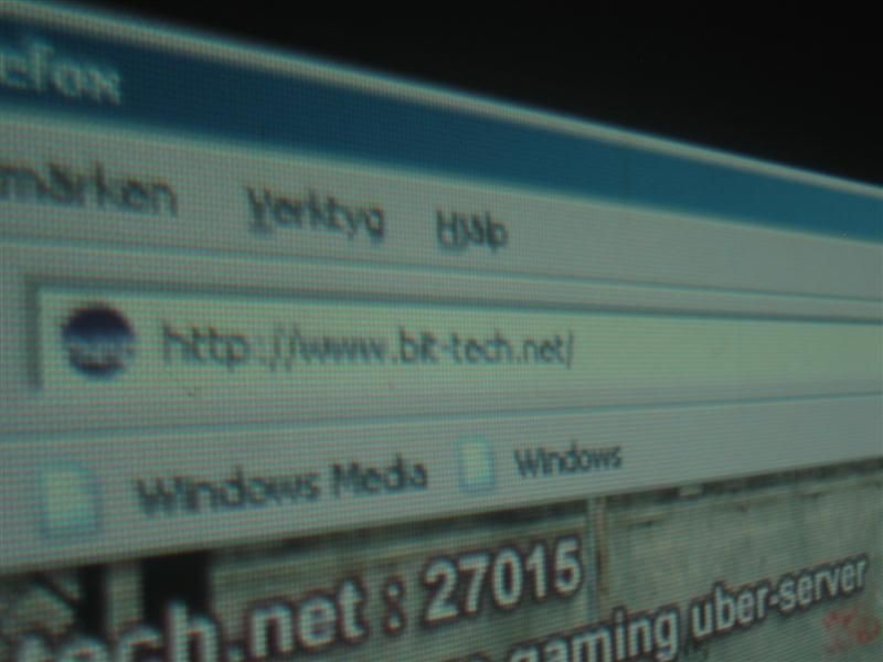
the image is projected on a white wall.. It is relly not the best option. I would rather have used my projector screen that I made a couple of months ago, but I dont have acces to that at the moment, because this is just a temporary home. So It will have to do for now.
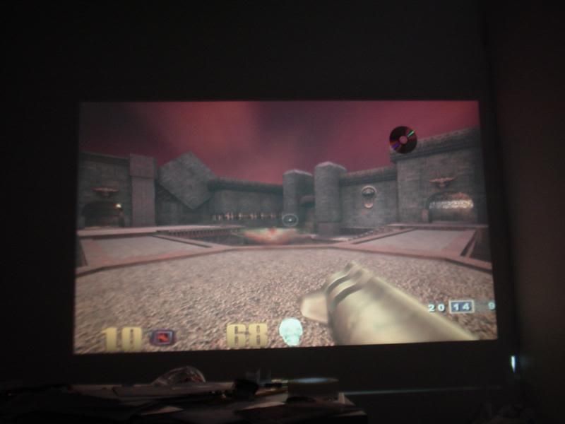
The image size is around 70" i would guess.. you got a cd in the uper right corner in some pics to get a feeling of the size.
The resolution is 800x480 on the screen but my desktop is at 1024x768 on these pictures so thats why there is a little bit of blur on the closeup shots of the text.
There will be more pictures to come. But this will do for now 🙂
Was hard to take good pictures that gives a tru image of the brightness. But I think these where most "relistic" ones.

(CLICK TO ZOOM)

(CLICK TO ZOOM)

(CLICK TO ZOOM)

(CLICK TO ZOOM)

(CLICK TO ZOOM)

(CLICK TO ZOOM)
Some good old quake III..

(CLICK TO ZOOM)
ill be back 🙂
/GNU
the image is projected on a white wall.. It is relly not the best option. I would rather have used my projector screen that I made a couple of months ago, but I dont have acces to that at the moment, because this is just a temporary home. So It will have to do for now.
The image size is around 70" i would guess.. you got a cd in the uper right corner in some pics to get a feeling of the size.
The resolution is 800x480 on the screen but my desktop is at 1024x768 on these pictures so thats why there is a little bit of blur on the closeup shots of the text.
There will be more pictures to come. But this will do for now 🙂
Was hard to take good pictures that gives a tru image of the brightness. But I think these where most "relistic" ones.
(CLICK TO ZOOM)

(CLICK TO ZOOM)

(CLICK TO ZOOM)
(CLICK TO ZOOM)
(CLICK TO ZOOM)

(CLICK TO ZOOM)
Some good old quake III..
(CLICK TO ZOOM)
ill be back 🙂
/GNU
Brother, your Projector IS an Inspiration to perfection.
your DIY skills and ingenuity is truely of very high order.
thanks for sharing your skills and methods of working with metal.
And your photography is not bad either!!!
A true DIYer learns from every project ,and I am sure your project will inspire many, to not only aim for a decent projection, but also make sure it looks good in the home theatre.
YOU HAVE RAISED THE BAR a few notches as far as i am concerned
Hope it gives you many hours of enjoyment!
This is my embarrsing little effort!
http://www.diyaudio.com/forums/showthread.php?threadid=87959&referrerid=50386
- Status
- Not open for further replies.
- Home
- General Interest
- Everything Else
- The Moving Image
- DIY Projectors
- The_Gnu's Lilliput projector (lot of pics)