Thanks for your summary! I will try to implent this.
Also on the voodoo... I try to stay away from this as much as possible, since in my opinion this is ruining the whole concept of music which is mostly intended to be shared and enjoyed with many people. And this whole concept of "the more expensive the better sounding" irritates me a lot. Don't get me wrong I appreciate quality, but using a 500$ RCA cable or a copper-cooler and insisting it influences the sound is just wrong.
cheers!
> IMO, it would be better with both on the same PCB, or
> reduction in power board size by moving at least a couple
> of those capacitors on the amp board.
so, the most important thing is,
never share Signal-GND with GND from the power supply.
I see this on the board here.
The central grounding is not on the amplifier board,
but on the power supply board
> The yet tiniest single-sided LM3886
use SMD, 1206 is not a big problem 😉
Attachments
^ I was not making that point (valid or not), mine was, there is no sense in putting excessive capacitance on a PSU board remotely located, especially spending more for lower ESR caps, when what achieves the implied goal is more capacitance on the amp board.
On the PSU board, 50 to 120Hz (when AC freq is doubled through the bridge rect.) is easily managed with 10K uf or less capacitance, what remains is the current changes caused by the audio itself, current changes relative to the chipamp itself. Capacitors are filters, best placement is where the power NEEDS filtered, not on a modularized arbitrarily decided upon location.
BUT, I am speaking about electrical function, not about subjective perceptions of what sounds best - as always that requires auditioning to decide for one's self.
using 33V and 2.4V Zeners in series.
Look at the datasheets for your chosen Zeners.
What is the maximum and minimum currents for the two different Zeners?
Is there an operating current overlap that allows both Zeners to regulate while passing the same current.
If there is then it is imperative that at all working voltages and currents that the two Zeners remain in that narrow range of regulating operating current.
Far easier and better to use two equal value Zeners (or nearly so) or just a single Zener, eg 2*18V or 18V + 20V 400mW Zeners.
Minimum regulating current ~10% * 400mW / 20v >=2mA
Maximum regulating current (worst case) 100% * 400mW / 20V <=20mA
^ I am wondering if you are considering the pass transistor, that this is a transistor drive not a shunt regulator.
Those were the zeners I had, I don't recall the current now as it was a few years ago I built this, but I'm sure I checked that at the time, probably typical 500mW parts. The 430 ohm resistor limits current. Current range overlap? That's an odd concept to me for zeners when dealing within their current capability and considering rail voltage would never drop low enough that you didn't have a few mA through R1 and R2. The range doesn't seem so narrow when you are working with known values like input voltage range and a resistor value you choose based on transistor hfe, these are darlington transistors so required current is reduced, but of course it could use two separate transistors instead.
Working within a known range of voltages, two different zeners can work ok, and I didn't use a single because as I wrote I used the parts I had on hand at the time.
While I am not 100% certain, a file search in an amps project folder found 1N5257, a 500mW part. Remember this isn't a theoretical PSU (anymore), it's been powering an amp built a few years ago. I should add, this isn't the entire power rail schematic for the amp, only what is on the PSU board with an AC filter board before it and a few thousand uF bulk, and decoupling caps on the amp board.
Last edited:
I don't think you have understood what I was trying convey.
I'll be more specific now that you have specified 500mW Zener.
The 33V Zener has a maximum current of 15.1mA.
The same Zener will start to run out of regulation at about 10% of maximum current. Some devices can get down to about 5%, but most have gone around the knee in the V vs I curve at these very low currents.
Expect your 33V Zener to have a minimum current for effective regulation of about 1.5mA.
The range of currents for the 33V Zener is ~1.5mA to 15.1mA
The 2.4V Zener has a maximum current of 208mA.
The minimum current for effective regulation will be somewhere in the range 10mA to 21mA.
The overlap in operating current for the two very different Zeners is >10mA to 15.1mA, if the 33V Zener is effectively regulating at 5% of maximum current.
There could equally well be no overlap in operating current for your two chosen very different Zeners.
You need to look up the datasheets for your Zeners, but far easier to use same Zeners for your circuit.
I don't expect you to do that now.
I expect you to inform readers about your experiences and to point out any shortcomings that you should be capable of identifying so that others do not copy your mistakes.
Your circuit will operate as a crude, not particularly well regulated power source. It is not a good example of how it could or should be done.
^ I wasn't trying for some kind of super regulator, and it's unneeded on chipamps with high PSRR. My point was as stated, to use parts I already had to drop voltage on a transformer with higher voltage than I wanted, within the context of building a PSU to suit one's own goals, not someone else's goals.
I don't consider it a mistake to build something that works, has higher current margin than a LM338 subcircuit would, and sounds good. If you are claiming "it could be better", sure, the same can be said about any typical gainclone, turning a simple project into more and more time, work, expense, etc. Thing is, idealizing a circuit doesn't necessarily make it sound better.
I don't consider it a mistake to build something that works, has higher current margin than a LM338 subcircuit would, and sounds good. If you are claiming "it could be better", sure, the same can be said about any typical gainclone, turning a simple project into more and more time, work, expense, etc. Thing is, idealizing a circuit doesn't necessarily make it sound better.
I have implemented the changes in the PSU, taken from the high-cap-guide and adjusted resistor-sizes. The design is pretty similar to the guide, so this should be ok. I'm not totally sure R3/4 are enaugh with 0.25W but I think not much current will flow trough them...
Parts-list:
C1-C6: 4700uF, 35V
C7,C8,C11,C12: 100nF
C9,C10: 120nF
R1,R2: 4.7k 0.25W
R3,R4: 1R 025W
PSU+:
Parts-list:
C1-C6: 4700uF, 35V
C7,C8,C11,C12: 100nF
C9,C10: 120nF
R1,R2: 4.7k 0.25W
R3,R4: 1R 025W
PSU+:
An externally hosted image should be here but it was not working when we last tested it.
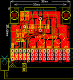
hurtz, your R3/C10 and R4/C9 aren't doing anything in the circuit because you have them going from ground to ground instead of from positive rail to ground and from negative rail to ground.
Also, R1` and R2 need to be larger than 0.25W, with a rail voltage at only ~35V they would exceed 0.25W dissipation and it's usually a good idea to run resistors lower than the rating, I aim for closer to half power. I'd go for a minimum of 1W or better 2W resistors there, OR increase the ohm value instead. I would also move them a little further away from capacitors since they are a constant heat source. If this board is going to have plated holes you can get away with the small traces to those resistors but otherwise I would make the trace larger (wider especially at the hole) to help deal with the heat which can delaminate the trace over time unless you're using 2oz or more copper PCB.
Also, something is wrong with the C1-C6 capacitor polarity "+", it doesn't match the output connector polarity markings.
Last edited:
Hi !,
whoops... too much zoom I guess..
R1/2 will only be aroud 0.144W since I only have 26V. So they should be fine.
Thanks for your corrections!
amp+:
whoops... too much zoom I guess..
R1/2 will only be aroud 0.144W since I only have 26V. So they should be fine.
Thanks for your corrections!
amp+:
An externally hosted image should be here but it was not working when we last tested it.
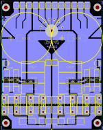
One other thought is why remove the copper on the ground trace(s)? What I mean is, a PCB starts out entirely copper that has to be removed but only if it *needs* to be removed. It could cover everywhere on the board there isn't a positive or negative trace. What you have will work, but you could leave the entire board covered with copper and have lower impedance (leave pos & neg rails wider too). I don't know if you are making it yourself or paying for a commercial board but with DIY, one other bonus is it uses less etching acid to remove only the copper you need to, although it takes a much beefier soldering iron to solder it later, but there can be thermal reliefs around the holes to help with that.
Hmm I see your point, I'm doing them myself with toner transfer. I guess I will keep it this way, since some people have reported problems with large copper pour areas. Also there will be a lot of narrow pitches which could be a problem for the DIY'ers with less accurate ways to etch.
cheers!
cheers!
Hi Hurtz,
Just a couple of comments. While you're technically correct that R1 and R2 will be at about 70% of rated power dissipation (assuming no more than 10% over voltage), you should realize that 1/4 watt resistors have a very small surface area too radiate heat, in this application they will run quite hot. I would recommend increasing to at least 1/2 watt rating for that reason. I also recommend that you split the trace between the two grounds at the output to keep the ground currents isolated from each other, that will prevent the positve and negative supplies from interacting with each other.
Mike
Hi agian,
I meant to say split the grounds at the input side where the transformer secondaries connect, I just woke up and my old brian isn't fucntioning at it's normal 10% capacity yet. 😉
Mike
I meant to say split the grounds at the input side where the transformer secondaries connect, I just woke up and my old brian isn't fucntioning at it's normal 10% capacity yet. 😉
Mike
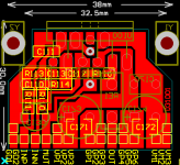
Thanks! Good point with the surface area! Have updated them to be 2W (I have better access to 2W's and there's still a lot of space left) PSU has been updated.
I wonder, if I also disconnect the Grounds on the output, and join them on the AMP, I would have a "true" star-ground, would this bring any actual advantages? Sorry if this has been discussed before, but I still have a little trouble properly imaginang how the currents behave.
cheers!
P.s. the trace-length between PSU and AMP will not exceed 10cm.
Hi Hurtz,
In my last post I corrected the mistake I made in my first post when I refered to the output side of the board, I meant to say the input side, sorry about that. I'm assuming your transformer has independant secondaries with no common center tap. Obviously, if it does have a center tap you won't be able to keep the input grounds separate. It's not a huge deal, I just think it's better to keep them separate if you can.
Mike
Hi Mike!
Yes I understood correctly, my transformer has two separate coils, and now the grounds join on the output of the PSU, what I meant was, what if I join those grounds on the AMP (instead of the output of the PSU)? So, seperated grounds on in- and output!
cheers!
Yes I understood correctly, my transformer has two separate coils, and now the grounds join on the output of the PSU, what I meant was, what if I join those grounds on the AMP (instead of the output of the PSU)? So, seperated grounds on in- and output!
cheers!
- Status
- Not open for further replies.
- Home
- Amplifiers
- Chip Amps
- The yet tiniest single-sided LM3886?