Ok, I owe you 2 more Mel’s then. I will need to place a refill order soon.
No problem. The boards are amazing!
Must have been a nightmare to get all that routing done. And the through-holes. Oh MY! 😱
Regards,
-Michael
The boards are the product of JPS64's amazing talents as a professional designer. We are very lucky to have his board designs. The 3 million vias connecting the top and bottom sides are plated through and coated with gold. These perforated boards probably are equivalent to 4oz copper thickness in impedance. If you hold the board up to the light, you can actually see through it quite well.
May i ask,
“25VA/18v is fine for general purpose preamp. If you want to drive a 0dB gain amp like F4 to clipping, you will need the 22v version.”
The trimmers how can i configure?
Thank you in advance
“25VA/18v is fine for general purpose preamp. If you want to drive a 0dB gain amp like F4 to clipping, you will need the 22v version.”
The trimmers how can i configure?
Thank you in advance
Just set them to midpoint and then adjust so that output voltage is what you want plus make sure that there is enough drop to get low ripple control. Usually this is about 2.5v to 3v minimum. The voltage changes with load too so adjustments made without Melbournes installed will be a bit higher than with them in place.
I guess I don't know really understand your question - which I thought was "The trimmers how can i configure?"
The only trimmers are in the PSU portion, and they set the voltage dropout in the cap multiplier.
So, if your intent is to drive a F4 amp to clipping, you need to be able to put out 40Vpp (thats's 25w into 8ohms).
The minimum voltage rail require for 40Vpp output is 45V total or +/-22.5V at the rails of the Melbourne. Assuming a 3v drop across the cap Mx ea (2 x 3v) is 6v drop. Add 45v+6v = 51V total or +/-25.5Vdc before the cap Mx. 25.5Vdc requires a transformer of at least 18v assuming no load. Given that this is a Class A preamp with 40mA of current draw, there wil be a little (2-3v) sag, so make it 20vac (marginal) and 22vac for sure will work.
The setup the cap Mx trimpots to about center position, make sure the Melbourne modules work (measure bias current across test points on 8.2R resisotr). It should measure around 328mV +/-20mV.
Now just voltmeter and measure voltage output of cap Mx as you adjust trimpots to set voltage drop. Make sure it is at least 2.5v, 3v is fine, and if you are using Talema 35VA 22vac trafo, you will see that you can easily get +/-25.5vdc output.
Hope that helps.
Sorry for my English, but the answer is awesome and exactly what I wanted to know
Thank you !!!
Thank you !!!
Hi X, same as batty, my Yarra boards were delivered today as well, they look even better in real life.
Great news. Those are some big boards aren’t they? Now hold them up to the light and look through them. They are “see thru” boards. JPS64 did a superb job and we are all very lucky in DIY to benefit from his professional experience.
Interest in Wayne’s 2017 BA Linestage daughterboard for Yarra motherboard?
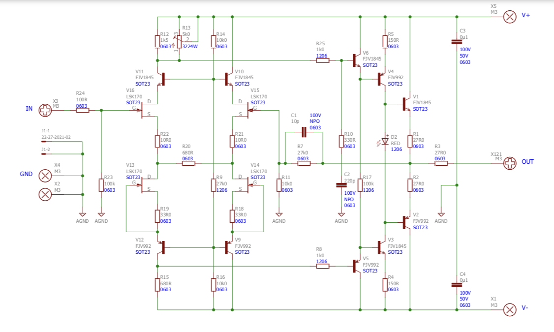
JPS64 has come up with a mostly through hole (TH) implementation of Wayne’s 2017 BA Linestage preamp in a Yarra-compatible format. This makes it easy to test out this preamp by simply popping it into your existing Yarra. The Yarra also makes preamp “rolling” possible. Here is the schematic (for SMT version). The TH version still uses the four JFET SOT23’s soldered underneath. They are easy to solder. The rest are TH and we have upgraded the output devices to state of the art TO126 Toshiba TTA004C and TTC0004 devices which handle the heat dissipation better and also allow some tweaking for higher bias currents to drive even headphones if desired. Alternatively, one could even install this as the input stage for the M2X amp.
Schematic:
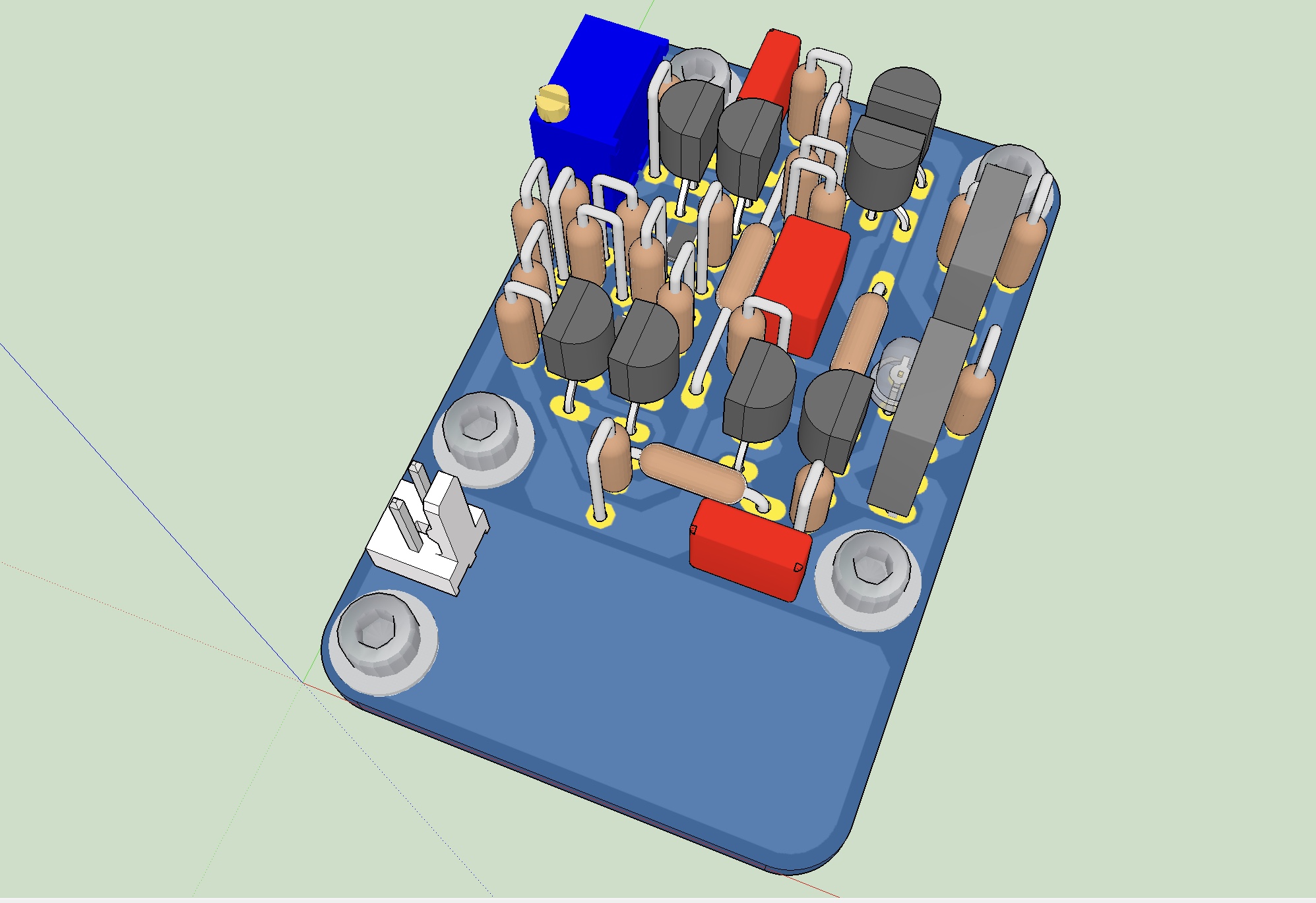
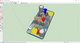
3D render:
JPS64 has come up with a mostly through hole (TH) implementation of Wayne’s 2017 BA Linestage preamp in a Yarra-compatible format. This makes it easy to test out this preamp by simply popping it into your existing Yarra. The Yarra also makes preamp “rolling” possible. Here is the schematic (for SMT version). The TH version still uses the four JFET SOT23’s soldered underneath. They are easy to solder. The rest are TH and we have upgraded the output devices to state of the art TO126 Toshiba TTA004C and TTC0004 devices which handle the heat dissipation better and also allow some tweaking for higher bias currents to drive even headphones if desired. Alternatively, one could even install this as the input stage for the M2X amp.
Schematic:
3D render:
Attachments

Last edited:
I’d be interested in Wayne’s 2018 BA Linestage DB for Yarra.
In addition to the Melbourne, it would be nice to have another “flavor” to play with.
In addition to the Melbourne, it would be nice to have another “flavor” to play with.
- Home
- Group Buys
- The YARRA Preamplifier/HPA for Melbourne DB Group Buy