yep, no doubt your choice of patterns has to do with habit at your day job and favorite libraries for that where better tools/reflow are more easily accessed.
also I meant rectifier above, not inductor, I had inductance on the brain. the 1210 cap regulator reference bypass and the bridge on the power supply boards I found the most challenging, as its compounded by the direct thermal connection to the solid ground and power planes.
how profoundly does the addition of thermal relief effect impedance at the currents/slewrate we are talking about? I ask this not just for this board, but the PCBs i'm currently working on use solid planes for everything including input and output. they will be reflowed most likely so not such a big deal, but just for curiosity.
Update on kit ETA
Hi. I'm one of the people who missed the original group buys who is eagerly anticipating the release of the new kits. Any update of when they will be available? Thanks!
Hi. I'm one of the people who missed the original group buys who is eagerly anticipating the release of the new kits. Any update of when they will be available? Thanks!
I think there an outstanding number of lurkers who are eagerly awaiting another batch... (including me 😀)
Still working on your website Owen ?
Still working on your website Owen ?
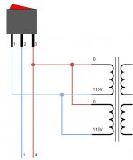
I figured out this darn switch within my 'wire' is causing me grief.
It's a Defond 12A 115vac, it's wired up between iec inlet and my transformer.
It's a Defond 12A 115vac, it's wired up between iec inlet and my transformer.
This is how I wired up the switch...
I guess I should ground it to the case.
An externally hosted image should be here but it was not working when we last tested it.
I guess I should ground it to the case.
This is how I wired up the switch...
I guess I should ground it to the case.
Is that the wiring that did not work? Was the bulb constantly lit regardless the switch position? If it was, you were using wrong pair of pins on the switch. Try the center pin and the one on the other side.
There could also be a safety issue with the wiring. You're supposed to put a switch following the Live terminal of the IEC socket, but it seemed in the diagram the switch is on the Neutral.
The ground pin of the IEC socket should be wired to the chassis.
The switch worked (neon bulb) lit when I pushed the rocker up (and off when down).
Just wasn't getting any ac to my transformer from the switch.
I guess I should be using neutral (black) to the switch.
Just wasn't getting any ac to my transformer from the switch.
I guess I should be using neutral (black) to the switch.
The switch worked (neon bulb) lit when I pushed the rocker up (and off when down).
Just wasn't getting any ac to my transformer from the switch.
I guess I should be using neutral (black) to the switch.
with only two pins on the switch wired up you should never see the light turns on. You were definitely using a wrong pair of terminals.
If your switch is of Defond ARC series, wire Live from IEC to pin 1, Neutral from IEC to pin 3, transformer 115 to pin 2, transformer 0 to pin 3.
Yes,..... except that the IEC is still backwards. The terminal on the IEC that the back wire is attached to is Live, and the one has the red is Neutral.
ok, here's the switch that's driving me nuts.
An externally hosted image should be here but it was not working when we last tested it.
what size were you using? you might have to look for another reason the fuses are popping ... the current draw on this amp is VERY small; 0.5A @ 120V is 60W, the amp draws less than 5W, and I doubt the inrush current is too huge. I would think 0.2A would be more than enough.
- Home
- Amplifiers
- Headphone Systems
- "The Wire" Ultra-High Performance Headphone Amplifier - PCB's