it being? there are 3 different headamps alone called 'the wire'. yes you can, with at least +/-6.5->8vdc, but the average battery will not last long at all due to the current draw from the buffers, in fact many will be unable to give enough current. you need to have an even number of batteries connected in series and connect ground to the junction between the center ones. but this may create problems interfacing with your source as the ground potential will be elevatedCan you power up "the wire" with a couple of batteries? What is the power requirement for it?
the headphone impedance will also govern the minimum voltage that can be used as the buffers will swing closer to the rails into low impedance with higher supply voltage, with very low supply like +/-5vdc the swing into low impedance will be vastly reduced and may be not enough
Last edited:
Whadja expect?
It IS a low noise design, after all 😀
given the number of these pcbs out there its all a bit quiet
It IS a low noise design, after all 😀
Particleman14:
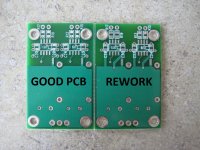
That's a rework board you have there, without the rework done on it!!!!!
You got one of each with your kits, since you ordered a full SE-SE kit and a rework board. The proper SE-SE board was in the bag with the kit, and the rework SE-SE board was either in a separate bag, or loose in the box.
With the rework boards, the PSU rails are reversed on both front end op-amps and that's why it's shorting.
You need to either re-build on the second board, or perform the correct modifications to the board you have to make it work correctly.
Luckily, they must have some sort of reverse polarity protection on those op-amps, because they seem to survive this sort of abuse. I would imagine if you just modified the board then everything will probably work just fine.
I've attached a picture of how I did mine, but I have since thought of cleaner ways to do it. The second picture attached is probably the cleanest I can think of:
1. Cut each trace on the red lines using a utility knife.
2. Peel the entire trace off the board between the two cut points.
3. Solder in some pre-formed solid copper wire (22-24AWG) along the black lines. Tack one end to the capacitor pad, and the other two the appropriate vias or via.
Cheers,
Owen
Attachments


Last edited:
haha!! i totally didnt even think of that.
yes they seem to be particularly hardy dont they? i would still try and clean up that board a bit, there is definitely a short waiting to happen here
since the bottom copper pour looks like it is a ground pour, does this make the top copper pour live? either way i would clean it up a bit, see the notes in the pic attached below
@ wolfston .....lol
Attachments
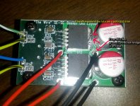
I also dont like the look of the left signal input wire, you really should tin the wire before you solder it, those freying loose wires could easily turn into a short. not a problem now, but not difficult to become one
and the OCD in me is having issues with you using ground coded wiring for signal lol green with white stripe is an international code for ground; thats more about me than you
and the OCD in me is having issues with you using ground coded wiring for signal lol green with white stripe is an international code for ground; thats more about me than you
Last edited:
what about his shorted signal inputs and outputs, i'm having problems visualizing how the rail swap would cause this?
That is a bit of a concern... Let's hope they were just measured incorrectly. If he simply had the meter set to continuity then the meter may have seen the 10k input resistor and made the beep sound.
As a result of the above issues, I have updated the build Wiki with info on the rework boards, and added note about the unconnected GND pad on the BAL-SE baords.
If you're building one of these projects, it's a must read:
"The Wire" Headphone Amp Build Wiki - diyAudio
Cheers,
Owen
As a result of the above issues, I have updated the build Wiki with info on the rework boards, and added note about the unconnected GND pad on the BAL-SE baords.
If you're building one of these projects, it's a must read:
"The Wire" Headphone Amp Build Wiki - diyAudio
Cheers,
Owen
yes lets hope some sort of error happened there. its unlikely to be as you say though, i'm unaware of any DMM that would beep on 10k for continuity test, i've never experienced that and just to double check i just tested a 2k2 on my fluke and my cheapo ratshack type and i get open circuit on continuity while i get the expected 2k2 on ohms. on mine it has to be pretty low resistance before it will call it continuity, like a few hundred ohms
edit: has to be less than 100R on the cheapo meter, 100R just measures 100 but no beep, 68R beeped
edit: has to be less than 100R on the cheapo meter, 100R just measures 100 but no beep, 68R beeped
Last edited:
lmao omg... I thought the other board was the rework!. Looks like I'll have some reworking to do lol... will let u guys know this weekend.. oo dear..
ya sorry about the hasty wiring qusp🙂 I just grabbed whatever wire I had on me🙂
ya sorry about the hasty wiring qusp🙂 I just grabbed whatever wire I had on me🙂
Last edited:
It IS a low noise design, after all 😀
I have yet to build mine. I am awaiting a trip to the electronics shop to get a new tip for my iron, awaiting arrival on my toroid and once I have it all I plan to make a nice wooden box cnc's out of 30mm ply. It's have a steal base for added mass. I don't want the unit sliding around when I stick the headphones in.
Success! So I reworked the board and voila everything seems to be working a-ok. I'm glad the error was so simple🙂 anyways here are some rework pics. gunna be enjoying this guy till the week starts! cheers!
![IMG_20120129_000015[1].jpg](https://www.diyaudio.com/community/data/attachments/245/245570-0700891aa1787778a441c1abc9c300f6.jpg?hash=BwCJGqF4d3 "IMG_20120129_000015[1].jpg")
it sounds better than it looks! lol
it sounds better than it looks! lol
Hi OPC,
I saw @The Wire Wiki, you still have 20 BAL-SE PCB, so would you count me for 3 BAL-SE PCB?
thank you
FJ
I saw @The Wire Wiki, you still have 20 BAL-SE PCB, so would you count me for 3 BAL-SE PCB?
thank you
FJ
i think this is not correct and up to date info, if you read the thread you will see most pages in the last 20 pages or so i have told someone there are no PCBs left.
so i guess i'll say it again, there are no PCBs left
so i guess i'll say it again, there are no PCBs left
Actually it would have to be an old version of the wiki that you're looking at to see 20 bal-se remaining. opc updated the wiki nearly a fortnight ago to reflect the closed status and NO PCBs LEFT status.
See the wiki here - "The Wire" Headphone Amp GB - diyAudio
See the wiki here - "The Wire" Headphone Amp GB - diyAudio
yeah probably cached
no worries JustFJ, you only asked once and it hasnt been mentioned in the last few pages as its all been build queries/troubleshooting. unlike previous times when its already posted on the same page
no worries JustFJ, you only asked once and it hasnt been mentioned in the last few pages as its all been build queries/troubleshooting. unlike previous times when its already posted on the same page
I am missing the 4 pieces of 10uf caps in my SE-SE kit. Can I just get regular 10uf 16v X5R SMD 1206 cap for it?
I have powered it up with the 4 caps and it sounds allright. DC offset is fractions of mv.
Thanks! 🙂
I have powered it up with the 4 caps and it sounds allright. DC offset is fractions of mv.
Thanks! 🙂
I wouldnt no, as the psu is offboard and one of the best things about the wire is the ground/decoupling as this keeps noise right down. x5r are not so flash. i'm sure opc will send you some caps, suppose you could use those temporarily
I have the pcb from the first groupbuy which is the same as on the OP and I finally getting around to put this thing together.
I have a question in regards to the 49600 before I solder them on the pcb. A1 & A2, am I suppose to put some type of thermal conductive paste on the pads?
Trying to be really careful not to make mistakes, thanks
I have a question in regards to the 49600 before I solder them on the pcb. A1 & A2, am I suppose to put some type of thermal conductive paste on the pads?
Trying to be really careful not to make mistakes, thanks
- Home
- Amplifiers
- Headphone Systems
- "The Wire" Ultra-High Performance Headphone Amplifier - PCB's