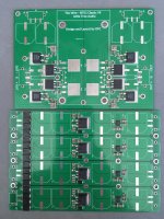
Owen, thanks for confirming C21-C24. You sure do nice work, these PCB's are really nice.
Phew, that's all I want to do for today. Those caps are a little tricky to get the solder under. I did all this with a MS-20 20w soldering iron and a lot of ChipQuick flux. Now all I need is those 390-400r D-Pak's.
oop's, I just swapped the L49880 for the ADP7142. (must be for another project?)
Phew, that's all I want to do for today. Those caps are a little tricky to get the solder under. I did all this with a MS-20 20w soldering iron and a lot of ChipQuick flux. Now all I need is those 390-400r D-Pak's.
oop's, I just swapped the L49880 for the ADP7142. (must be for another project?)
Attachments
Last edited:
Owen, thanks for confirming C21-C24. You sure do nice work, these PCB's are really nice.
Phew, that's all I want to do for today. Those caps are a little tricky to get the solder under. I did all this with a MS-20 20w soldering iron and a lot of ChipQuick flux. Now all I need is those 390-400r D-Pak's.
oop's, I just swapped the L49880 for the ADP7142. (must be for another project?)
Great soldering and parts alignment!!!
Nice work damuffin!
Do
What is the best practice to solder those surface mount power transistors? Should there be a paste between a transistor and a board? Same question about resistors.
Regards,
zz
Regards,
zz
Definitely not a stupid question...
The absolute best way to do it would be to use a dollop of low melting temp solder paste (like ChipQuick) under the big pad and then flow it with heat applied to the tab/pad after soldering the two leads in place and locking the position.
If you don't have solder paste, you can always just heat the whole thing and flow solder onto the pad and the tab. This is what I always do if I'm building these by hand. While it's all hot, I lift the tab slightly to let solder flow beneath, then push it back down to let it cool.
Thermally, having solder flowed completely beneath the pad is always best, but you can get sufficient flow just applying solder to the junction as you would with any other part.
Regards,
Owen
I ordered the wire pcb from Owen a while back. I have yet to receive the pcb, which shows it has been shipped. I emailed and sent him a pm, with no response. If I don't get response here shortly. I'll be unwinding this transaction with PayPal.
Hi Erik,
Patience, please. Owen is really not the kind of guy who publicly swindles you out of a couple of bucks for fun.
Do you have confirmation by a shipping company?
If so, why would Owen be to blame?
If not, how do you know it's really shipped if you couldn't reach Owen?
You can clearly see Owen respond within this thread, so he's certainly not hiding from you.
Please keep in mind that this is not a real commercial business (yet) – and on top of that, it's vacation time.
Instead of a public threat, why not simply ask nicely?
Others have done so with success.
Cheers,
Sebastian.
I have yet to receive the pcb
Patience, please. Owen is really not the kind of guy who publicly swindles you out of a couple of bucks for fun.
which shows it has been shipped
Do you have confirmation by a shipping company?
If so, why would Owen be to blame?
If not, how do you know it's really shipped if you couldn't reach Owen?
I emailed and sent him a pm, with no response.
You can clearly see Owen respond within this thread, so he's certainly not hiding from you.
Please keep in mind that this is not a real commercial business (yet) – and on top of that, it's vacation time.
If I don't get response here shortly. I'll be unwinding this transaction with PayPal.
Instead of a public threat, why not simply ask nicely?
Others have done so with success.
Cheers,
Sebastian.
I have had the opportunity to meet Owen several times in person. He is very generous with his time and has freely donated lots of goodies to the Ottawa DIY group. He has 2 ankle biters at home, a new house a stressful new job plus its summer time here in Ottawa and summer is only a couple of weeks in length. The city of Ottawa is closing the beaches this coming Sunday. He answers tons of emails on this forum and others. He is also supporting these projects and developing, testing and perfecting new projects. If he says he sent you the boards. They have been sent. Wait a bit.
I ordered the wire pcb from Owen a while back. I have yet to receive the pcb, which shows it has been shipped. I emailed and sent him a pm, with no response. If I don't get response here shortly. I'll be unwinding this transaction with PayPal.
Hi Eric,
Your board shipped out along with all the others in the last batch. They shipped out on Friday July 31st, and you should be getting them this week sometime.
I often leave the "where are my boards?" PMs for last since the answer is usually "in the mail" or "about to go in the mail". More often than not they've arrive before I even get a chance to respond. Sorry I didn't get around to answering you sooner.
All boards ship out via letter mail which saves everyone quite a bit on shipping. Shipping with express post and tracking would quadruple shipping prices and I generally assume nobody wants to pay more for shipping than the boards. As a result, I don't have any tracking numbers to offer. If your order doesn't arrive, I can always send another one out. So far, of the few hundred orders I've shipped, only two have failed to arrive.
Thanks to both sek and multisync for the kind words 🙂
Regards,
Owen
Hi Owen,
can I still make an order?
I wrote down some boards into the spredsheet, but don't know, if you still deliver them. In this case I would like to pay immediatelly.
Regards,
Stammheim
can I still make an order?
I wrote down some boards into the spredsheet, but don't know, if you still deliver them. In this case I would like to pay immediatelly.
Regards,
Stammheim
Hi Guys,
Just a heads up that I opened a new thread this evening for the latest addition to "The Wire" series. It's a phono preamp, and all the information is available here:
http://www.diyaudio.com/forums/analog-line-level/278590-wire-balanced-phono-preamp.html#post4423477
I have boards in-stock if anyone is interested. Use the sing-up sheet as usual.
More to come in the next few days!
Regards,
Owen
Boards arrived 10 days after posting. Thank you.
For the iV convertor, I'm having trouble finding the 35w 180R and 390R resistors in any quantity less than 500.
Does anyone know a source of small quantity in Europe. Digikey seems only to offer 500+ here.
Alternatively, can I buy parts separate from the boards from Owen??
Thanks in advance
Simon
For the iV convertor, I'm having trouble finding the 35w 180R and 390R resistors in any quantity less than 500.
Does anyone know a source of small quantity in Europe. Digikey seems only to offer 500+ here.
Alternatively, can I buy parts separate from the boards from Owen??
Thanks in advance
Simon
Hi guys,
does anybody know, where the LT3042 is available?
I found it only at LT yet, but delivery is about 50$ to Germany.
Best regards,
Stammheim
does anybody know, where the LT3042 is available?
I found it only at LT yet, but delivery is about 50$ to Germany.
Best regards,
Stammheim
Last edited:
Hi Owen, My boards have arrived as well, many thanks.
I am having the same problem as spm. I cannot find a source of the 35W resistors, except at Digikey with a MOQ of 500. Does anyone know of any other suppliers, preferably in Europe?
Otherwise, Owen, would it be possible to buy a parts pack separate from the boards?
Thanks
Stefan
I am having the same problem as spm. I cannot find a source of the 35W resistors, except at Digikey with a MOQ of 500. Does anyone know of any other suppliers, preferably in Europe?
Otherwise, Owen, would it be possible to buy a parts pack separate from the boards?
Thanks
Stefan
Sabrosa:
Sorry... I missed your order on the sheet somehow. I have plenty of boards and will send you a payment request tonight!
Hey Owen, thanks for sending the NTD1 purchase link!
I was trying to decide whether to order the parts kit and wanted to ask you about adjusting the NTD1’s gain, as my amplifiers are single ended input Odyssey Kismet monoblocks with 1VRMS sensitivity and 22k input impedance.
With the NTD1 v2 circuit you previously mentioned halving the resistance of resistors 13, 14, 28, 29 (200R) and 16, 17, 25, 26 (400R) to get half the gain. In the simulation you ran for Crom, who was looking to run a dual mono setup, the values came out to 89R and 188R with +/- 32v rails for 1VRMS (2VRMS in dual mono).
Does a similar modification hold true for the v3 circuit with resistors 3, 4, 17, 18 (180R) and 9, 10, 11, 12 (390R)? Even though the v3 rails have been reduced from +/- 45V to +/- 38V, I’m guessing they will still need to be further reduced in this case, similar to how v2 was reduced to +/- 32V?
Would any other circuit modifications be required? It looks like v2’s 30k9 resistors were already reduced to 20k in v3 and R20 and R23 (100k) were removed in v3.
My next step is deciding how to perform the balanced to single ended conversion. I was originally thinking I’d use a 600:600 transformer like the JT-11-BMCF from Jensen or something from Cinemag to keep things simple without having to add an additional bipolar power supply and transformers and deal with the heat and space requirements that comes with each. However, I admit that I’m intrigued by using the BAL-BAL at unity gain and having the option to include a balanced headphone out.
My main priority is the best possible performance and sound out of the 2-channel system. Any thoughts on transformers versus the BAL-BAL in this situation? Will the BAL-BAL still require coupling capacitors here? I saw the DC coupled NTD1 referenced again recently and thought these modifications might be similar.
If I did go BAL-BAL route, does anyone have suggestions on narrowing down power supply choices between PSU V2, LT3042 Parallel Reg PSU, and Salas SSLV Shunt?
What is current consumption of NTD1 I/V converter, I wonder?
In standard trim, with 200R and 400R resistors and 38V rails, you're looking at 100mA of current draw per leg, 200mA current draw per channel, or 400mA current draw total for a stereo NTD1.
It should be noted that the regulators for the NTD1 PSU are guaranteed for 250mA, so you don't really have much headroom if you want to lower the resistance and increase the current draw.
Sabrosa:
I'll cover your question next.
Regards,
Owen
Hi Sabrosa,
Lots of material to cover here, but I appreciate that you've clearly done your homework 🙂
You have an interesting set of ideas, and some of them have touched on a few topics I've played with while working to improve the NTD1.
Let's get started:
All of the above is exactly correct, but your particular setup gives you some very interesting options you might want to consider.
The NTD1 tends to work better and better as you lower the values for the two resistors in each leg (180R, 390R). It also works better and better as you pump more current through each leg. The downside to doing this is that the gain is reduced, and the output voltage becomes too low to directly drive a power amp. The other downside is dissipation, which can quickly get out of hand.
Since you already planned on using a BAL-BAL to do your BAL-SE conversion, why not use the op-amp for what it does best (voltage gain) and the NTD1 for what it does best (I/V conversion)?
If that's the case, then you can drop the resistor values right down to 45R and 98R in each leg. This will give you 500mVRMS of differential output from the NTD1 which isn't a problem because you can just set the gain of the BAL-BAL to 2 or 4 or whatever gives you the output voltage you want. It also means you can run +/-18V rails which means you can use a much lower noise supply like the parallel LT3042 to run both the NTD1 and the BAL-BAL.
But wait, there's more! Despite running lower rails, you're actually feeding about 200mA of current through each leg, which is twice the amount of a normal NTD1. This makes the FET very happy, and combined with the lower input impedance, drives distortion even lower. Power dissipation remains about the same at 29W.
Hold on... it gets better. Now that the rails are down at 18V, the output terminals of the NTD1 are each at 9V, and this is well within the common-mode voltage allowance of a BAL-BAL populated with either an OPA1632 or an LME49724. That means you can lose the coupling caps between the output of the NTD1 and the BAL-BAL and go DC coupled.
The above description, in a nutshell, is the DC coupled NTD1 I've been working on. It measures incredibly well, and sounds fantastic.
Downsides:
If you DC couple, then you will get a transient on startup and you might need a relay to mute the outputs until everything has settled. You might also get some DC on the outputs, although it will be small. If that's not your thing, then keep the output caps and AC couple the NTD1 to the BAL-BAL while keeping everything else the same. This setup does not suffer from large transients on startup, and will not have any DC at the output.
Yes, the resistors feeding the gate from the positive rail will need to be reduced further to accommodate the 18V rails. They need to be chosen along with the pot to get about 6-7VDC at the gate of the FET when the pot is at the midpoint. Otherwise, everything stays the same.
This is a tougher question, and one that is mostly going to come down to personal preference. There's no doubt the BAL-BAL on the output, in the setup described above, will measure considerably better than a transformer. Some people do prefer the band limiting and relatively benign low order distortion from the transformer, and I know several people have used the NTD1 with transformers on the output and have reported very good results.
I personally would go for an active element like the BAL-BAL over a transformer, but that's just me.
If you do decide on a transformer, then again, it might be best to get your voltage gain from the transformer (use a step-up 1:2) and use the same low output version of the NTD1 described above to drive it. One coupling cap to prevent DC from saturating the transformer, although you should be able to adjust things well enough not to need a cap at all.
I will let others cover this one as I'm only familiar with two of these supplies 😉
Regards,
Owen
Lots of material to cover here, but I appreciate that you've clearly done your homework 🙂
You have an interesting set of ideas, and some of them have touched on a few topics I've played with while working to improve the NTD1.
Let's get started:
I was trying to decide whether to order the parts kit and wanted to ask you about adjusting the NTD1’s gain, as my amplifiers are single ended input Odyssey Kismet monoblocks with 1VRMS sensitivity and 22k input impedance.
With the NTD1 v2 circuit you previously mentioned halving the resistance of resistors 13, 14, 28, 29 (200R) and 16, 17, 25, 26 (400R) to get half the gain. In the simulation you ran for Crom, who was looking to run a dual mono setup, the values came out to 89R and 188R with +/- 32v rails for 1VRMS (2VRMS in dual mono).
Does a similar modification hold true for the v3 circuit with resistors 3, 4, 17, 18 (180R) and 9, 10, 11, 12 (390R)? Even though the v3 rails have been reduced from +/- 45V to +/- 38V, I’m guessing they will still need to be further reduced in this case, similar to how v2 was reduced to +/- 32V?
All of the above is exactly correct, but your particular setup gives you some very interesting options you might want to consider.
The NTD1 tends to work better and better as you lower the values for the two resistors in each leg (180R, 390R). It also works better and better as you pump more current through each leg. The downside to doing this is that the gain is reduced, and the output voltage becomes too low to directly drive a power amp. The other downside is dissipation, which can quickly get out of hand.
Since you already planned on using a BAL-BAL to do your BAL-SE conversion, why not use the op-amp for what it does best (voltage gain) and the NTD1 for what it does best (I/V conversion)?
If that's the case, then you can drop the resistor values right down to 45R and 98R in each leg. This will give you 500mVRMS of differential output from the NTD1 which isn't a problem because you can just set the gain of the BAL-BAL to 2 or 4 or whatever gives you the output voltage you want. It also means you can run +/-18V rails which means you can use a much lower noise supply like the parallel LT3042 to run both the NTD1 and the BAL-BAL.
But wait, there's more! Despite running lower rails, you're actually feeding about 200mA of current through each leg, which is twice the amount of a normal NTD1. This makes the FET very happy, and combined with the lower input impedance, drives distortion even lower. Power dissipation remains about the same at 29W.
Hold on... it gets better. Now that the rails are down at 18V, the output terminals of the NTD1 are each at 9V, and this is well within the common-mode voltage allowance of a BAL-BAL populated with either an OPA1632 or an LME49724. That means you can lose the coupling caps between the output of the NTD1 and the BAL-BAL and go DC coupled.
The above description, in a nutshell, is the DC coupled NTD1 I've been working on. It measures incredibly well, and sounds fantastic.
Downsides:
If you DC couple, then you will get a transient on startup and you might need a relay to mute the outputs until everything has settled. You might also get some DC on the outputs, although it will be small. If that's not your thing, then keep the output caps and AC couple the NTD1 to the BAL-BAL while keeping everything else the same. This setup does not suffer from large transients on startup, and will not have any DC at the output.
Would any other circuit modifications be required? It looks like v2’s 30k9 resistors were already reduced to 20k in v3 and R20 and R23 (100k) were removed in v3.
Yes, the resistors feeding the gate from the positive rail will need to be reduced further to accommodate the 18V rails. They need to be chosen along with the pot to get about 6-7VDC at the gate of the FET when the pot is at the midpoint. Otherwise, everything stays the same.
My next step is deciding how to perform the balanced to single ended conversion. I was originally thinking I’d use a 600:600 transformer like the JT-11-BMCF from Jensen or something from Cinemag to keep things simple without having to add an additional bipolar power supply and transformers and deal with the heat and space requirements that comes with each. However, I admit that I’m intrigued by using the BAL-BAL at unity gain and having the option to include a balanced headphone out.
My main priority is the best possible performance and sound out of the 2-channel system. Any thoughts on transformers versus the BAL-BAL in this situation? Will the BAL-BAL still require coupling capacitors here? I saw the DC coupled NTD1 referenced again recently and thought these modifications might be similar.
This is a tougher question, and one that is mostly going to come down to personal preference. There's no doubt the BAL-BAL on the output, in the setup described above, will measure considerably better than a transformer. Some people do prefer the band limiting and relatively benign low order distortion from the transformer, and I know several people have used the NTD1 with transformers on the output and have reported very good results.
I personally would go for an active element like the BAL-BAL over a transformer, but that's just me.
If you do decide on a transformer, then again, it might be best to get your voltage gain from the transformer (use a step-up 1:2) and use the same low output version of the NTD1 described above to drive it. One coupling cap to prevent DC from saturating the transformer, although you should be able to adjust things well enough not to need a cap at all.
If I did go BAL-BAL route, does anyone have suggestions on narrowing down power supply choices between PSU V2, LT3042 Parallel Reg PSU, and Salas SSLV Shunt?
I will let others cover this one as I'm only familiar with two of these supplies 😉
Regards,
Owen
- Home
- Vendor's Bazaar
- "The Wire" Official Boards for All Projects Available Here! BAL-BAL, SE-SE, LPUHP