Hi Owen,
Those HV regs look ideal for the ultra low distortion oscillators from mickevich on ebay. What're the physical dimensions on the regulator board?
I have a couple (1kHz and 10kHz) of those oscillators I was going to power off an old LPUHP PSU v1 with LM317HV but haven't got around to that yet and these look so much nicer 😀
Cheers,
Chris
Congrats Owen! As you have found out with the first one, taking delivery is easy (most of the time), it's the lifelong care that they require that really tests you... 😀Everything was on hold for a little while to make time for a second little one 🙂
Hi Owen,
any news about the estimated shipping date of the NTD1 V4 and the NTD1 PSU?
I would buy two pieces bundled with all key parts. Perfect soldering is no problem for me.
Should I solder one of your ten boards you already got and test it for you?
kind regards,
Horst
any news about the estimated shipping date of the NTD1 V4 and the NTD1 PSU?
I would buy two pieces bundled with all key parts. Perfect soldering is no problem for me.
Should I solder one of your ten boards you already got and test it for you?
kind regards,
Horst
Hi Owen,
when will be the shipping date of the NTD1 V4 and the NTD1 PSU? What will be the price of one set with
all parts? Will there be a build Guide?
Thanks and all the best,
Nick89
when will be the shipping date of the NTD1 V4 and the NTD1 PSU? What will be the price of one set with
all parts? Will there be a build Guide?
Thanks and all the best,
Nick89
Hi Guys,
I figured it was time for a quick update on where all the new boards are at since I've had several questions about the NTD1 and some of the new (X)PUHP amplifier series boards.
Generally good news on all fronts, and pretty much everything is ready to ship, or within a week of being ready to ship. I will be adding the new boards to the order spreadsheet, and creating some new threads and Wiki pages to support them.
I'll toss up three "teaser" pictures here, with three additional dedicated posts for each new project to follow shortly.
Introducing the NTD1 V3, NTD1 PSU, the MPHUP and the MPUHP PSU and the HPUHP!
Cheers,
Owen
Attachments
ever going to sell completed boards after soldering 8 LPUHP i don't have the will power to do that again took me hours and hours
Yes... each of these boards will be offered with all SMD components mounted as well as bare boards.
Pricing for SMD populated boards will take an extra day or two to get together as it requires component costs, some of which are quite volatile.
I've soldered well over 400 LME49610 IC's at this point so I know what you mean about losing the will to continue 😉
Cheers,
Owen
Pricing for SMD populated boards will take an extra day or two to get together as it requires component costs, some of which are quite volatile.
I've soldered well over 400 LME49610 IC's at this point so I know what you mean about losing the will to continue 😉
Cheers,
Owen
Owen,
And I bet you thought you could get away with showing an alternative AVCC regulator on that Buff-II... BUSTED!
ADM7150? Or something magical?
And how do you like it?
Inquiring minds and such!
Greg in Mississippi
And I bet you thought you could get away with showing an alternative AVCC regulator on that Buff-II... BUSTED!
ADM7150? Or something magical?
And how do you like it?
Inquiring minds and such!
Greg in Mississippi
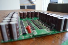
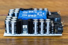
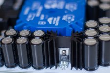
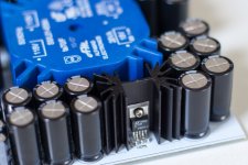
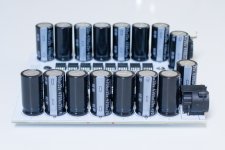
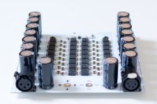
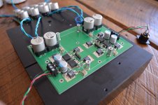
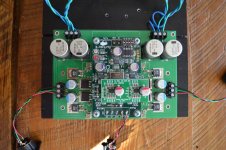
Let's kick things off with the MPUHP:
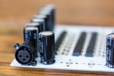
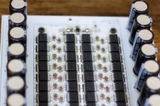
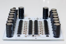
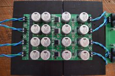
The MPUHP is a fully bridged version of the LPUHP with four times the number of output buffers (32 in total!) and a front end based on a single OPA1632 differential op-amp.
It's good for 50W into 8 ohms continuous, and has the same or better performance than the LPUHP.
Noise is very low at 5.75 uVRMS (unweighted, 22kHz BW) with a gain of 20dB. Lower noise is possible with lower gain settings.
Maximum output current is 2.9 ARMS and maximum output voltage is 20VRMS.
Output impedance is an incredibly low 1.2 milliohms across the entire audio band, and frequency response is perfectly flat from DC to well over 500kHz.
The amplifier dissipates roughly 15W at idle and works on +/-18V regulated rails.
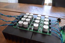
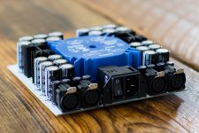
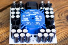
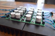
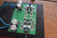
Along with the MPUHP comes the MPHUP PSU. It was specifically designed to power the MPUPH and provide robust regulated low noise rails to the output buffers.
The PSU uses a pair of LT1185 regulators and over 146,000uF of capacitance. There's another 132,000uF local to the amplifier for a total of 278,000uF per channel. It is strongly recommended to use one PSU per amplifier if you want full output power. It is, however, fine to power other auxiliary items such as headphone amplifiers, DACs or other relatively low power devices from the same supply as the amplifier.
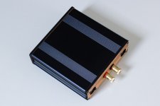
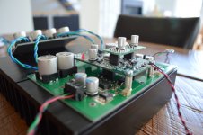
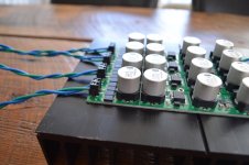
Both the MPUHP and MPHUP PSU are designed to slot into a standard 160mm x 160mm enclosure. I use BOX enclosures BEX 4, but Hammond also makes a suitable enclosure that is similar in size.
Heatsinking for the amplifier is accomplished through a simple 5mm thick aluminum plate which will need to be provided by the end user. This plate, along with a thermal pad, couples heat to the chassis which provides sufficient heatsinking. Other solutions exist, and it's also easy to directly mount a correctly size heatsinks to the bottom of the amp.
Attached here are some pictures of the amp and PSU, and the next post will be measurements.
Cheers,
Owen
The MPUHP is a fully bridged version of the LPUHP with four times the number of output buffers (32 in total!) and a front end based on a single OPA1632 differential op-amp.
It's good for 50W into 8 ohms continuous, and has the same or better performance than the LPUHP.
Noise is very low at 5.75 uVRMS (unweighted, 22kHz BW) with a gain of 20dB. Lower noise is possible with lower gain settings.
Maximum output current is 2.9 ARMS and maximum output voltage is 20VRMS.
Output impedance is an incredibly low 1.2 milliohms across the entire audio band, and frequency response is perfectly flat from DC to well over 500kHz.
The amplifier dissipates roughly 15W at idle and works on +/-18V regulated rails.
Along with the MPUHP comes the MPHUP PSU. It was specifically designed to power the MPUPH and provide robust regulated low noise rails to the output buffers.
The PSU uses a pair of LT1185 regulators and over 146,000uF of capacitance. There's another 132,000uF local to the amplifier for a total of 278,000uF per channel. It is strongly recommended to use one PSU per amplifier if you want full output power. It is, however, fine to power other auxiliary items such as headphone amplifiers, DACs or other relatively low power devices from the same supply as the amplifier.
Both the MPUHP and MPHUP PSU are designed to slot into a standard 160mm x 160mm enclosure. I use BOX enclosures BEX 4, but Hammond also makes a suitable enclosure that is similar in size.
Heatsinking for the amplifier is accomplished through a simple 5mm thick aluminum plate which will need to be provided by the end user. This plate, along with a thermal pad, couples heat to the chassis which provides sufficient heatsinking. Other solutions exist, and it's also easy to directly mount a correctly size heatsinks to the bottom of the amp.
Attached here are some pictures of the amp and PSU, and the next post will be measurements.
Cheers,
Owen
Attachments
-
 ItemA-5.jpg619 KB · Views: 328
 -
 ItemA-7.jpg528.5 KB · Views: 337
 -
 ItemA-9.jpg481.5 KB · Views: 319
 -
 ItemA-13.jpg490.1 KB · Views: 280
 -
 ItemA-1.jpg648.7 KB · Views: 373
 -
 ItemC-38.jpg422.3 KB · Views: 414
 -
 ItemB-18.jpg541.4 KB · Views: 384
 -
 ItemB-16.jpg461.2 KB · Views: 354
 -
 ItemB-15.jpg440.7 KB · Views: 374
 -
 ItemB-14.jpg399.2 KB · Views: 575
Total height of the amp itself is limited by the caps until you get down to the XLR connectors. Minimum height with low profiles caps would be 30mm. Standard height with the suggested caps would be 38mm.
If you wired the connectors off board and laid the caps down sideways you could achieve the thickness of the caps, so basically 18mm. I would imagine at that point though, other parts like input, and output connectors would limit the height.
Regards,
Owen
If you wired the connectors off board and laid the caps down sideways you could achieve the thickness of the caps, so basically 18mm. I would imagine at that point though, other parts like input, and output connectors would limit the height.
Regards,
Owen
Now for measurements. I'll do this in two separate parts; one for the amplifier and one for the PSU.
First up is the amp itself. Measuring something with distortion this low is a bit of a challenge, and calls for some slightly different techniques. The analog generator in the AP I have is limited to around 0.00012% THD but that's only at about 500mV output, and only at 2kHz, and only on a few of the 8 channels.
I was able to improve on this by using a BII and the NTD1 instead of the AP's built in generator. Where the AP generator has a second harmonic generally at around -126dB and a third harmonic at around -115dB, the NTD1 can achieve -126dB for the second harmonic, and -128dB for the third. This first measurement is the MPUHP being driven by the NTD1 from the AP's digital output, and back into it's analog input. Again, this distortion test is limited more by the NTD1 than the MPUHP.
Here are measurements and what each is:
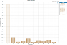
1. Distortion Product Ratio at -10dBFS into the NTD1 (650mV into the MPUHP, 6.5V out of the MPUHP into 8 ohms)
2. THD Ratio at -11dBFS into the NTD1. The MPUHP is on channel 6, the output of the NTD1 is on channel 5. The distortion is lower for the MPUHP because at these levels, the AP confuses noise with distortion, so the higher output level from the MPUHP causes it to measure a little better (better SNR)
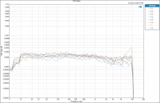
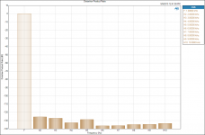
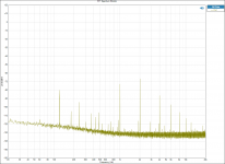
3. FFT of the amplifier output with no input. The noise floor sits below -150dB from 500Hz up to 20kHz, and gently rises from 500Hz to 20Hz but never exceeds -140dB. The only correlated noise visible is some of the upper line harmonics with one at 180Hz (-143db) one at 300Hz (-148dB) and the rest are basically buried in the noise below -149dB.
4. The remaining measurements are all done using just the AP output, so some will appear slightly worse than with the NTD1. This measurement is done at 4.5V output from the amp into an 8R load.
5. Measured output noise with no input. CH1 is the MPUHP, and CH2 is the AP looped back to itself.
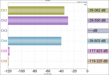
6. SNR at 1W into 8R. CH1 is the MPUHP and CH2 is the AP loopback
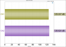
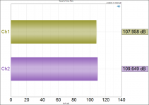
7. SNR at 50W into 8R. CH1 is the MPUHP and CH2 is the AP loopback
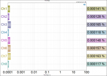
8. THD ratio at 5.5V output. Can you spot which channel the MPUHP is on, and which are just loopbacked from the AP? Didn't think so 😉. The MPUHP is on channel 6.
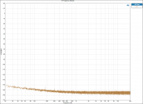
9. THD sweep with all AP channels looped back except 6 which has the MPUHP driven at 5.5V output. The MPUHP is buried among the loopback channels up to about 7kHz where it starts creeping above the AP distortion floor.
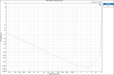
10. THD+N ratio swept from 10uW up to 50W into an 8 ohm load.
PSU measurements to follow!
First up is the amp itself. Measuring something with distortion this low is a bit of a challenge, and calls for some slightly different techniques. The analog generator in the AP I have is limited to around 0.00012% THD but that's only at about 500mV output, and only at 2kHz, and only on a few of the 8 channels.
I was able to improve on this by using a BII and the NTD1 instead of the AP's built in generator. Where the AP generator has a second harmonic generally at around -126dB and a third harmonic at around -115dB, the NTD1 can achieve -126dB for the second harmonic, and -128dB for the third. This first measurement is the MPUHP being driven by the NTD1 from the AP's digital output, and back into it's analog input. Again, this distortion test is limited more by the NTD1 than the MPUHP.
Here are measurements and what each is:
1. Distortion Product Ratio at -10dBFS into the NTD1 (650mV into the MPUHP, 6.5V out of the MPUHP into 8 ohms)
2. THD Ratio at -11dBFS into the NTD1. The MPUHP is on channel 6, the output of the NTD1 is on channel 5. The distortion is lower for the MPUHP because at these levels, the AP confuses noise with distortion, so the higher output level from the MPUHP causes it to measure a little better (better SNR)
3. FFT of the amplifier output with no input. The noise floor sits below -150dB from 500Hz up to 20kHz, and gently rises from 500Hz to 20Hz but never exceeds -140dB. The only correlated noise visible is some of the upper line harmonics with one at 180Hz (-143db) one at 300Hz (-148dB) and the rest are basically buried in the noise below -149dB.
4. The remaining measurements are all done using just the AP output, so some will appear slightly worse than with the NTD1. This measurement is done at 4.5V output from the amp into an 8R load.
5. Measured output noise with no input. CH1 is the MPUHP, and CH2 is the AP looped back to itself.
6. SNR at 1W into 8R. CH1 is the MPUHP and CH2 is the AP loopback
7. SNR at 50W into 8R. CH1 is the MPUHP and CH2 is the AP loopback
8. THD ratio at 5.5V output. Can you spot which channel the MPUHP is on, and which are just loopbacked from the AP? Didn't think so 😉. The MPUHP is on channel 6.
9. THD sweep with all AP channels looped back except 6 which has the MPUHP driven at 5.5V output. The MPUHP is buried among the loopback channels up to about 7kHz where it starts creeping above the AP distortion floor.
10. THD+N ratio swept from 10uW up to 50W into an 8 ohm load.
PSU measurements to follow!
Attachments
-
 Signal to Noise Ratio - 50W 8R.png48.5 KB · Views: 186
 -
 THD Ratio - 550mV input - CH6.png87.8 KB · Views: 183
 -
 THD Ratio - All Channels.png115.3 KB · Views: 216
 -
 THD+N Ratio vs Measured Level 7.5R.png90.2 KB · Views: 238
 -
 Signal to Noise Ratio - 1W 8R.png48.1 KB · Views: 181
 -
 Level - Output Noise - No Input - 22k BW.png62.2 KB · Views: 878
 -
 Distortion Product Ratio - 450mV input - 7.5R.png48.8 KB · Views: 864
 -
 FFT Spectrum Monitor - No Input.png94.1 KB · Views: 899
 -
 Distortion Product Ratio -11dB.png53 KB · Views: 880
 -
 Distortion Product Ratio -10dB.png48.2 KB · Views: 898
Now for the MPUHP PSU:
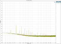
1. Negative rail FFT supplying MPUHP at idle
2. Positive rail FFT supplying MPUHP at idle
3. Positive rail FFT with amplifier delivering 10VRMS into 8 ohms.
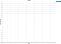
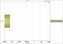
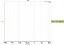
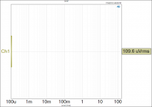
4. Output noise negative rail
5. Output noise positive rail
6. Output noise negative rail with amplifier delivering 10VRMS into 8 ohms.
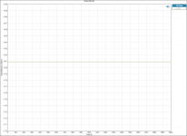
7. Scope monitor negative rail
8. Scope monitor positive rail
Next to the output of the MPUHP, these can look pretty noisy, but keep in mind that not having a single harmonic over -80dB makes the output of this power supply cleaner than that of most actual amplifiers! It's this nice clean supply that allows the MPUHP to achieve such a low noise floor at the output of the amp.
The PSU itself can be easily configured for 120V or 240V operation depending on where you populate the mains fuse on the PCB.
Later today I will post more details on the NTD1 V3 and the NTD1 PSU.
Cheers,
Owen
1. Negative rail FFT supplying MPUHP at idle
2. Positive rail FFT supplying MPUHP at idle
3. Positive rail FFT with amplifier delivering 10VRMS into 8 ohms.
4. Output noise negative rail
5. Output noise positive rail
6. Output noise negative rail with amplifier delivering 10VRMS into 8 ohms.
7. Scope monitor negative rail
8. Scope monitor positive rail
Next to the output of the MPUHP, these can look pretty noisy, but keep in mind that not having a single harmonic over -80dB makes the output of this power supply cleaner than that of most actual amplifiers! It's this nice clean supply that allows the MPUHP to achieve such a low noise floor at the output of the amp.
The PSU itself can be easily configured for 120V or 240V operation depending on where you populate the mains fuse on the PCB.
Later today I will post more details on the NTD1 V3 and the NTD1 PSU.
Cheers,
Owen
Attachments
-
 Scope Monitor - Positive Rail.png67.2 KB · Views: 155
 -
 Scope Monitor - Negative Rail.png66.1 KB · Views: 168
 -
 Output Noise - Positive Rail - 10VRMS OUT AMP.png52.8 KB · Views: 151
 -
 Output Noise - Positive Rail.png47.4 KB · Views: 170
 -
 Output Noise - Negative Rail.png53.1 KB · Views: 180
 -
 FFT Spectrum Monitor - Positive Rail - 10VRMS OUT AMP.png106.1 KB · Views: 162
 -
 FFT Spectrum Monitor - Postive Rail - Idle Load.png103.9 KB · Views: 183
 -
 FFT Spectrum Monitor - Negative Rail - Idle Load.png102.9 KB · Views: 238
Owen,
And I bet you thought you could get away with showing an alternative AVCC regulator on that Buff-II... BUSTED!
ADM7150? Or something magical?
And how do you like it?
Inquiring minds and such!
Greg in Mississippi
Sharp eyes Greg!
I actually didn't even notice that when I was taking these pictures!
It is a replacement AVCC regulator board for the BII (no idea if the BIII or SE uses the same pinout and spacing) using a pair of ADM7150 regs with 1000uF NR bypass caps. I also have a variant coming with the next board order that uses the new LT3042 thanks to a tip from hochopeper 🙂
It does have lower measured output noise and lower output impedance than the included shunt regs for the BII, but to be honest, I can't hear a difference between this and the stock one.
I was going to include these as a "gift with purchase" when people bought the NTD1 V3, but I'm not sure how many people are still rocking the BII like I am.
Does anyone know if the BIII and BIII SE use the same pinout and spacing as the BII for the AVCC regs?
Cheers,
Owen
Last edited:
Sharp eyes Greg!
I actually didn't even notice that when I was taking these pictures!
It is a replacement AVCC regulator board for the BII (no idea if the BIII or SE uses the same pinout and spacing) using a pair of ADM7150 regs with 1000uF NR bypass caps. I also have a variant coming with the next board order that uses the new LT3042 thanks to a tip from hochopeper 🙂
It does have lower measured output noise and lower output impedance than the included shunt regs for the BII, but to be honest, I can't hear a difference between this and the stock one.
I was going to include these as a "gift with purchase" when people bought the NTD1 V3, but I'm not sure how many people are still rocking the BII like I am.
Does anyone know if the BIII and BIII SE use the same pinout and spacing as the BII for the AVCC regs?
Cheers,
Owen
Dang! I was hoping it was a variant of the illusive OPC shunt. But it LOOKED like an ADM7150 unit.
Yup on the AVCC module BII-BIII compatibility, I don't have a BIII, but I know TP sells the same AVCC module for both.
Not sure if you had the original or revised AVCC. I have seen several reports of people really liking various ADM7150-based regs in this application.
And thanks for the tip on the LT3042... I will check it out!
Later!
Hi Owen,
Thank for updating the NTD1 as I have a BII with the TP IVY bridge and have been wanting to change it for a long while now. I would also be interested in your "gift" ...
I looked at the spreadsheet but am not seeing the PSU for it. I would very much like to order very soon so any help is appreciated. I also sent you a PM.
Thanks for all your help.
Bertrand.
Owen, i am also on the spreadsheet for the V3 NTD1 and will want the power supply as well, how do we proceed with the order, and are going to be supplying parts kits as I would like to solder myself, but am not sure about sourcing all parts.
Thanks!
Thanks!
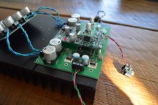
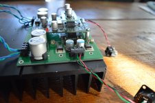
On to the NTD1 V3:
The first board available in this new series is the classic circuit with a few key improvements.
Overall, having built several variations, the classic circuit is still the best if you can manage to dissipate the heat, and you prioritize circuit simplicity and the kind of performance that by all rights should only be achievable with high feedback IC based circuits. In the case of the classic NTD1 though, this is accomplished with a mosfet and two resistors.
The new PCB has the following key changes:
- Using all SMD components makes mounting the entire PCB directly to a heatsink simple and very effective. No more aligning through hole fets and resistors with holes in the PCB, or trying to match the height with little pieces of FR4. With the new board, all you do is built it and screw it to a heatsink using a thermal pad. Job done. The resistors and mosfets are all D2 PAK types now which really opens up the FET options to the latest generation of parts, all of which are primarily made in D2 pack format. This layout also makes it easy for me to have these assembled as it's SMD line only, and one side only.
- The layout itself is tightened up considerably, and all signal traces are now shorter and better shielded.
- I've given up putting giant film caps on the PCB. There is space for two small 10mm polymer caps for output coupling, and these are easily shorted if you'd prefer to use giant film caps between the PCB output connector and the XLR jack you plan to use. I prefer the polymer caps, but to each his own.
- Bias adjustment pots are now mounted sideways so you can still access them regardless of your BII, BIII or BIII SE board arrangement.
- The PSU is now a completely separate PCB, allowing users to either go with their own PSU, or use the PSU separately for other projects.
- I have made up two separate BOMs for both the PSU and the NTD1. One is a budget friendly build with a very minimal reduction in performance, and one is a "suggested" build using parts that aim for the best possible performance while putting price second. That doesn't mean things are needlessly expensive, but instead that they are optimized for performance first. People who want to go above and beyond these two BOMs are always welcome to do so, but I leave that tinkering to the individual 🙂
Here are the circuit specific changes:
- Rails have been reduced to +/- 38VDC. This is a tradeoff between going to far better regulators, and slightly reducing bias current for the same given gain. Idle current is now 101mA if you use a 180R/390R resistor combo. It's slightly lower at 99mA if you go with the usual 200R/400R combo.
- The benefit of the above change is that power dissipation is now reduced from the usual ~45W down to about 30W.
- Mosfets are now Fairchild FDB52N20 parts which are the best I've found at the 100mA operating point. Both DK and Mouser have healthy stock.
- The resistor packages are suggested to be Reidon Thin Film parts from the PFS35 series of resistors. I'm going to have a custom production run done for the 390R/180R combo. These will be the only parts I will include as a kit option, as they are impossible to come by unless in larger quantities. If you go with the 200/400 combo, you have your pick of many resistor brands and types in that package. I'm using Caddock parts in the test bed.
Again, I'll create a Wiki just for this board with more details including the BOMs.
See more pictures attached!
Cheers,
Owen
Attachments
-
 DSC_0124.JPG288.8 KB · Views: 221
 -
 DSC_0123.JPG303 KB · Views: 323
 -
 DSC_0120.JPG409.2 KB · Views: 346
 -
 DSC_0119.JPG364.3 KB · Views: 323
 -
 DSC_0118.JPG367.1 KB · Views: 318
 -
 DSC_0117.JPG300.8 KB · Views: 265
 -
 DSC_0116.JPG324.2 KB · Views: 340
 -
 DSC_0114.JPG444 KB · Views: 392
 -
 DSC_0111.JPG362.4 KB · Views: 314
 -
 DSC_0126.JPG292.3 KB · Views: 213
Wow! Amazing job Owen!!
My friend told me about your update but it is only now that I had the time to check it out. I will definitely look into the NTD1 V3. I currently have the V2 version and I'm really satisfied but my 5V reg gets to almost 80 Celcius using the BII. I'm using Paul Hynes reg on the BII but the AVCC is still TP. How much would it be for your AVCC reg alone if I want to purchase 1?
Thanks
Do
- Home
- Vendor's Bazaar
- "The Wire" Official Boards for All Projects Available Here! BAL-BAL, SE-SE, LPUHP