I used ordinary LM317/337 for regulators. I added a zobel at the speaker output 10ohm and 0.1uf woked well, also an output inductor.
Hi guys,
I considered about my results from yesterday and I’d really like to understand what happens with my boards, so as an enthusiastic hobbyist with superficial understanding in electronics I red a lot about the LME-IC other electronic basics.
I have 6 boards in total with ALFET and NCD (?) transistors, all show the same behaviour, without effect if using an SMPS, a linear or a regulated ps, common or separate ps for the LME-IC. The boards are populated with parts from the last BOM (SE) and checked a few times for correct components and proper soldering.
Let me tell you what my Rigol oscilliscope shows me (GND-speakerout) biasing from 0 – 350mA:
0 – 80mA -> a flat line, no noise, no hum
80 – 150mA -> 10MHz sine increasing with bias current, a little noise noticeable, no interferrences
150 – 270mA -> same sine increasing with bias, noise is getting louder, interferrences sounding like grounding problem
270 – 320mA -> same sine, negative amplitude still grows, while positive amplitude moves slowly down. Both amplitudes seem to loose their nice curves and look like an amp is coming close to his input voltage.
Near 350mA -> speaker protection board is getting active
Disconnecting the speaker (open circuit) all results increase of about 10mA, but I’m able to increase bias to >1A without activating the speaker connection.
To be honest I’m out of my knowledge with that and hope, somebody has an idea to help my amps!
Many thanks and a nice day for you guys,
Stammheim
I was unaware that OPC had changed the component values. It was only yesterday that I saw that the newer sch of 13/9/2011 had new values and new components.While we're here Andrew, I've evidently missed the whole part about the circuit and component value changes.
Can you explain here why they were changed and why the extra compensation parts were used after originally the decision to not use them was made with good confidence? Is that 10uF part of the compensation or related to bias adjustment?
And the gate resistors dropped and to the same value rather than slight different values?
Thanks.
I was not party to any of these changes.
I lost interest when OPC started the Thread that mixed everything together like soup. I could not find anything I wanted.
I will look out my paperwork, yes I still work with paper and pencil.Are you able to elucidate as to what exactly was the error? Thanks.
I have borrowed a digital camera and should be able to post a pic or two explaining what was different between the green PCB traces and the original sch.
changing the bias changes the operating conditions. This can be sufficient to start an oscillation.Hi guys,
I considered about my results from yesterday and I’d really like to understand what happens with my boards, so as an enthusiastic hobbyist with superficial understanding in electronics I red a lot about the LME-IC other electronic basics.
I have 6 boards in total with ALFET and NCD (?) transistors, all show the same behaviour, without effect if using an SMPS, a linear or a regulated ps, common or separate ps for the LME-IC. The boards are populated with parts from the last BOM (SE) and checked a few times for correct components and proper soldering.
Let me tell you what my Rigol oscilliscope shows me (GND-speakerout) biasing from 0 – 350mA:
0 – 80mA -> a flat line, no noise, no hum
80 – 150mA -> 10MHz sine increasing with bias current, a little noise noticeable, no interferrences
150 – 270mA -> same sine increasing with bias, noise is getting louder, interferrences sounding like grounding problem
270 – 320mA -> same sine, negative amplitude still grows, while positive amplitude moves slowly down. Both amplitudes seem to loose their nice curves and look like an amp is coming close to his input voltage.
Near 350mA -> speaker protection board is getting active
Disconnecting the speaker (open circuit) all results increase of about 10mA, but I’m able to increase bias to >1A without activating the speaker connection.
To be honest I’m out of my knowledge with that and hope, somebody has an idea to help my amps!
Many thanks and a nice day for you guys,
Stammheim
Do you have an analogue oscilloscope that can read to over 10MHz? 20MHz or 50MHz are ideal for audio work. Some go as high as 100MHz and 200MHz but these scopes are getting beyond audio functionality.
he added the full Thiele Network, I only added the Zobel. There is just enough room between the big caps to fit a "flat" version of an R+C on the top side of the PCB.added a zobel at the speaker output 10ohm and 0.1uf woked well, also an output inductor.
The coil+damping resistor can go into the speaker lead.
Last edited:
changing the bias changes the operating conditions. This can be sufficient to start an oscillation.
Do you have an analogue oscilloscope that can read to over 10MHz? 20MHz or 50MHz are ideal for audio work. Some go as high as 100MHz and 200MHz but these scopes are getting beyond audio functionality.
he added the full Thiele Network, I only added the Zobel. There is just enough room between the big caps to fit a "flat" version of an R+C on the top side of the PCB.
The coil+damping resistor can go into the speaker lead.
I got the Rigol DS1104Z, which works up to 100MHz.
I have also got an old analogue Hameg, which shows the same results.
I got the Rigol DS1104Z, which works up to 100MHz.
I have also got an old analogue Hameg, which shows the same results.
OK - you constantly ignore my recommendations - I repeat it here for all others:
Laterals showing 10 - 20Mhz oscillation is a sign of unstable operating. Increase the Miller cap to 27pF, 33pF, 39pF to check when the oscillation stops. If this doesn't help you may have other problems too.
Had a similar problem during development of SA2016 lateral mosfet amplifier. Increasing the Bias started the oscillation because the operating conditions change as AndrewT correctly stated.
Last edited:
Astx: Oh man, I wanted – but forgot – to ask you what you mean with Miller cap, as there are no caps close to the Mosfets, but you of course mean LME‘s 20pF caps.
„Laterals showing…“ was the hint, that I understood, my failure amps show what you describe, makes sense to me.
Sorry, it’s not about ignoring but about missing contect in electronic knowledge.
Nevertheless... all my 6 amps are affected. How is it possible that I'm the only one who has that problem or is trying to get help???
Many thanks
Stammheim
Some might be afraid to ask in case I come in to give my answers.................. How is it possible that I'm the only one who has that problem or is trying to get help???............
Answers that they may not want to hear.
Some might be afraid to ask in case I come in to give my answers.
Answers that they may not want to hear.
I'm open for ANY kind of answers that make me come closer to my objectives. And when I can lear something at same time... isn't that great?!
Great to see that those Mica's are only available at the big distributors. Very cheap delivery from the states. NOT. 😉
the capacitor to change is C79 20pf to a higher value till the oscillation stops, as was mentioned above.
you can put the zobel 10ohm 0.1uf cap under the board at the speaker terminals.
you can put the zobel 10ohm 0.1uf cap under the board at the speaker terminals.
you are not the only one affected. I had oscillation as well with long speaker leads. The amp worked fine on the bench but not in the living room.
Refering to the "noise like ground problem" Stammheim mentions, I got a similar problem.
It was not with the same amp, but it was caused by EMI from the toroid transformer.
With increased bias the field around the transformer propably got bigger and got into the grounding on the pcb's.
Shielding did solv it. Bigger distance may work also.
Just a thought 🙂
Regards
Figge
It was not with the same amp, but it was caused by EMI from the toroid transformer.
With increased bias the field around the transformer propably got bigger and got into the grounding on the pcb's.
Shielding did solv it. Bigger distance may work also.
Just a thought 🙂
Regards
Figge
'The error between the PCB and the sch was around R46, R46, R54 and the traces to the signal return.
Because the traces are built into the multilayer PCB, it took a little detective work to come up with what in the end was a very simple modification to correct the error.'
Andrew, can you be more specific about this? I measured the connections but I don't see any strange things. I got the green board and used the last schematic (the google drive one 2011, I believe).
Does a Zobel decrease the „cable to speaker“ problem?
One of my first assumptions was a transformer issue, that’s why I tried an external transformer, external ps, external SMPS, seems to have no influence. On the other hand I couldn’t explain a 10MHz sine to myself.
For a better understanding:
Testing different Miller caps the goal is to eliminate the 10MHz sine to zero? How does a perfect out-signal look like?
Is biasing from 0 – 1A the right way, while taking care for the outcoming signal on the scope?
Is there a theoretical way (calc) to define the correct cap value? I saw the Mica cap is available in steps by 1.
I’d like to avoid to need another order from Mouser in case I’ll find out to need a value between the orderer caps, or maybe a bigger value. What happens with a „too big“ value?
I try a lot of testing, but there are often things I cannot explain to myself 😉
Regards
Stammheim
The larger the Miller capacitor the less bandwidth you have. Too large a value and you start decreasing the high frequencies in the audio band.
Look at an old computer monitor or old transistor radio and you will find several pico farad capacitors.
there are several ebay listings for multi valued capacitors. I bought a selection of capacitors and resistors for a few dollars.
The zobel eliminated the speaker cable problem. I don't know for 100% if it was the cables or the crossover in the speakers that caused the problem.
It is not unusual for an amplifier to oscillate under different conditions.
There is a way to calculate the correct value but you have to know the open loop phase margin of the circuit. We don't know that.
Too large a value and you start decreasing the high frequencies in the audio band.
Do we speak about several uF or another 10pF more than the optimum capacity?
I wonder about the ratio between capacity and bandwidth…
Do we speak about several uF or another 10pF more than the optimum capacity?
I wonder about the ratio between capacity and bandwidth…
- Without a zobel filter from speaker output to speaker ground this amp isn't stable! (100nF in series with 10R)
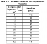
- Try to add a simple and cheap 10pF or 15pF parallel to the current 20pF to check if oscillation stops till full bias range! Affects the slew rate too - but to find the error it is ok to try this. (attached picture from LME49830-AN1850 "snaa058a.pdf")
- If this doesn't help try to add C80 e.g. 100nF.
BR, Toni
Attachments
Last edited:
The amplifier output Zobel provides a load at high frequency. This applies whether cables are attached or not.Does a Zobel decrease the „cable to speaker“ problem?
The problem with some amplifiers is that the gain can increase at high frequencis if there is no load attached. This higher gain can make the amplifier unstable or at least have lower stability margins than are not good for audio performance. The C part isolates the load from the amplifier at low frequencies and audio frequencies. The R part is the high frequency load.
setting the Cdom (Miller compensation cap) too high increases the feedback around the VAS/TIS stage. This reduces the OLG over a wider frequency range. It slows down the amplifier (lower slew rate) and carried to extremes can attenuate the high audio frequencies.One of my first assumptions was a transformer issue, that’s why I tried an external transformer, external ps, external SMPS, seems to have no influence. On the other hand I couldn’t explain a 10MHz sine to myself.
For a better understanding:
Testing different Miller caps the goal is to eliminate the 10MHz sine to zero? How does a perfect out-signal look like?
Is biasing from 0 – 1A the right way, while taking care for the outcoming signal on the scope?
Is there a theoretical way (calc) to define the correct cap value? I saw the Mica cap is available in steps by 1.
I’d like to avoid to need another order from Mouser in case I’ll find out to need a value between the orderer caps, or maybe a bigger value. What happens with a „too big“ value?................
Well, I have some Mica capacitors here and just wanted to solder any of them. I used my horizontal soldered transistors pcb's for testing and connected them with the 20pF for testing. NO interferences with the original setup!!!
Are the vertical soldered transistors causing the problem? They are completely the same pcb's (ok, using 2200uF instead of 1000uF as main capacitors), but the transistors are vertically soldered to be able to mount them directly on the radiator. So not using an L-shape.
Are they to near to the "big" capacitors? I also use steal screws instead of brass to mount them to the radiator. Is that also a point of failure?
Regards
Stammheim
Last edited:
- Home
- Amplifiers
- Solid State
- "The Wire AMP" Class A/AB Power Amplifier based on the LME49830 with Lateral Mosfets