I've heard of it referred to as "PMPO" on the side of some "600W computer monitors" that had a 5W wall wart powering them.
I think PMPO = "peak music power output"
I also think they measure it as the peak possible output power of a given channel, and then multiply it by whatever number of channels there are.
It's one my favourite audio quirks because it only tricks people who buy stereo systems based on how many watts they have 🙂
PMPO is the acronym that I've most commonly seen also, though I am sure some 'clever' marketing types have a few variations on the same just to keep us all chuckling.
I've heard of it referred to as "PMPO" on the side of some "600W computer monitors" that had a 5W wall wart powering them.
I think PMPO = "peak music power output"
I also think they measure it as the peak possible output power of a given channel, and then multiply it by whatever number of channels there are.
It's one my favourite audio quirks because it only tricks people who buy stereo systems based on how many watts they have 🙂
yeah dont they mostly only measure it with one channel powered? not just only measuring one channel, but actually only feeding one channel signal and loading it and then multiplying that by the number of channels, even if the psu is not rated to power all channels at anything close to that.
money for jam...
And they use peak instantaneous power and then they use low duty cycle signals and then they invent any bigger value to print on their packaging and advertising.
The figure that matters (if we are interested in maximum power) is the continuous sinewave power into the specified load when supplied with the specified mains voltage.
This should in my view be specified as a voltage into a resistive load @ a specified (lowish) distortion. This distortion could be around 0.1% for the max power/voltage measurement.
This should in my view be specified as a voltage into a resistive load @ a specified (lowish) distortion. This distortion could be around 0.1% for the max power/voltage measurement.
I would take that a step a further and capture the thermal capability of the amplifier as well, like the FTC power ratings do.
If you want to quote an amplifier as having 200W according to FTC standards, then the amplifier has to be able to supply 1/8th of the rated power for 1 hour, and then full power for 5 minutes without overheating, failing, or shutting down.
Having worked hard at my last job to get a class H amplifier to pass this test, I know how incredibly demanding a rating like that is. Running the amp at 1/8th power for an hour builds up a huge amount of heat, making it very difficult to supply full rated power for 5 minutes.
If an amplifier can do the above, then you know it truly lives up to the term "continuous".
It really would be wonderful if there were standardized power measurement ratings. I would agree with you Andrew that it should be 0.1%, sine wave RMS into a specified resistive load at a specified nominal line voltage. It should also be supplied at 2, 4, 6, and 8 ohm loads so people know both the current and voltage limitations of the amplifier.
I see more and more often, especially with class D amplifiers, thermal designs the depend heavily on the signal never being continuous. That to me is a scary way to design things and it leaves no room for running at a worst case scenario. It also results in misleading power ratings that are intended for "music power" and often have distortion ratings at 10%. If you look back at the scope captures of 10% distortion, you'll see that it's not something you want your amplifier doing!
Cheers,
Owen
haha.... sorry just having a giggle at the amount of time spent on psu related banter in this thread. cant wait for these supplies to get here, been tinkering with the linear supply plan for the second pair of amps, any opinions on coils in Class AB power supplies?
also opc: i've ordered some of those nice thin film caps for the power bandwidth setting, I couldnt get any higher than 12pf at mouser, so I actually bought double the number of 10pf, being so small, can you see any harm in stacking 2 on top of one another if done neatly? the inductance of such a small length of 'lead' shouldnt be resonant should it?
also opc: i've ordered some of those nice thin film caps for the power bandwidth setting, I couldnt get any higher than 12pf at mouser, so I actually bought double the number of 10pf, being so small, can you see any harm in stacking 2 on top of one another if done neatly? the inductance of such a small length of 'lead' shouldnt be resonant should it?
Last edited:
This is effectively a "test" of the heatsinks. It does not reveal any extra information about the amplifier performance.............If you want to quote an amplifier as having 200W according to FTC standards, then the amplifier has to be able to supply 1/8th of the rated power for 1 hour, and then full power for 5 minutes without overheating, failing, or shutting down.............
But I agree, for domestic listening 1/8 of maximum power is probably about the right level for a continuous rating of the heatsink capability. That will determine the temperature de-rated SOAR of the various output devices based on the Tc that the heatsinks can maintain with worst case Ta being applied.
For PA duty, I don't think 1/8 is an appropriate value, whether it's 1/3rd or 1/2 or 2/3rd is up for debate, but for this duty, active cooling can be implemented
Last edited:
10pF will be resonant @ some MHz frequency. But that should be so far outside the operating frequencies presented to the amplifier that it should be of no consequence. But test during/after the build to ensure the amp is behaving itself.
cool thanks Andrew, i'll do that. I just didnt want to replace the perfectly good 20pf mica that came in the kit with 10pf || 10pf higher quality parts, only to find i've made performance worse due to the 'lead' inductance
20pF in better or worse qualities !
Which part of the audio signal is be altered by that 20pF?
Which part of the audio signal is be altered by that 20pF?
20pF in better or worse qualities !
Which part of the audio signal is be altered by that 20pF?
this cap was singled out by opc as being the one part you might want to play around with if the power envelope suited the available values and these caps specifically were mentioned as an upgrade; so naturally i'm intrigued. given the position I actually gathered ALL frequencies might be effected
i'll wait for Owens comment; I bought some 12pf too
Thanks for your responses Owen, that's interesting 🙂
Thanks. Just in case you already sent the PM, I didn't receive it yet.Yes, I have enough left to send you 4. I'll send you a PM.
Yes I will be regulating; plan to put the regulators on the Vero with the LME. Most likely 317/337. I'm not sure how I'm going to do the heatsinking yet but I was talking to a friend who said he fitted another heatsink to the front of some chip, as well as the one it was bolted to, and it cooled the chip by another 15°C. I might use the whole back plate of the amplifier which will be insulated from the main heatsink, or maybe use some long plastic standoffs and bolt the assembly to the main sink.Absolutely, but that would have to be a regulated 95VOK for a higher voltage, 90 or 95V
I'll be bending one of the pins closer to the other so the surface mount chip will span them without any strain to the solder joints. I guess the capacitance between the LME pins and the surrounding ground plane would be taking some noise off the pins? Or acting as a shield or sink to radiated noise that's passing by. With the regulators up close to the LME there would be nearly no leads. I like to get the component pins onto the component pins or as near as practical.point to point skills....just solder it carefully between the required pins. I would guess that you'll end up with a slightly higher noise floor without the ground plane, and I would imagine decoupling would also be slightly worse since lead length is almost guaranteed to be longer.no PCB. Will that matter.
OK thanks, maybe the Alfets work a bit differently with their thinner substrate, or whatever it was, the lack of diodes, and in this case also the double die, maybe the current to charge what I presume is the two capacitances in the two dies is more? I still will have 6 dies or eight. It seems that with the older mostfets I have, provided there's enough current available to charge them, IIRC about 3.5mA each it would appear, they should be OK.The bias and voltage/current is definitely for the output devices and not the LME. The real benefits in terms of distortion reduction comes from the current. It would be safe to say that you'd probably see a slight improvement at 80V and 400mA versus 30V and 400mA, but it's not like the 80V version is going to measure better than the 30V version at 1A bias.the high bias current and lower and lower distortion
Last edited:
Maybe a small sidetrack for some but i thought this could be interesting to know for those still in search for chassis.
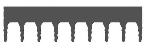
My 3U 400 mm depth pessante dissipante (modushop.biz) chassis has arrived and i'm positively surprised about the size and design of the heatsinks. The heatsinks included with the chassis have wavy fins like the picture shown. I haven't unwrapped it completely yet since i lack the space so it will stay in the package for now, but it weighs 10.5 kg in total so a fair amount of aluminum...
I ordered a separate 300x120x40 mm sink as well with straight fins otherwise they look the same. Here are the measurements of it:
The base slab is 7 mm thick, the fins are 3 mm at the bottom and 2 mm at the top, 10 mm spacing between the fins and it weighs in at 1.5 kg. To my surprise this is about the same as the conrad sinks qusp looked at. So i'm very pleased for the price so far, just hope everything fits together...
Attachments
IanAS,
The 317/337 regulators generate very little heat in this application. Even at 95V the the LME draws only 17mA. Assuming a 10 to 15 volt drop accross the regulators they will generate around 1/4 watt each. Mine are on very small heatsinks and stay very close to room temperature when operated continuously--barely warm to the touch.
Regards,
Neel
Thanks Neel for that info 🙂 Do you know if the 17mA pulsates at all? I saw that a couple more people vouched for SuperTeddyRegs and wondered if they'd have any effect here. I've not tried them anywhere yet. Seems they don't the voltage all that steady if the current demand varies and are suggested for DAC chips, etc. But it seems that some people seem to like them for the low voltage early stages of amplifiers. I've yet to read through the various threads about them.The 317/337 regulators generate very little heat in this application
Thanks Neel for that info 🙂 Do you know if the 17mA pulsates at all? I saw that a couple more people vouched for SuperTeddyRegs and wondered if they'd have any effect here. I've not tried them anywhere yet. Seems they don't the voltage all that steady if the current demand varies and are suggested for DAC chips, etc. But it seems that some people seem to like them for the low voltage early stages of amplifiers. I've yet to read through the various threads about them.
It's all in the LME49830 datasheet Ian:
POWER DISSIPATION AND HEAT SINKING
When in “play” mode, the LME49830 draws a constant
amount of current, regardless of the input signal amplitude.
Consequently, the power dissipation is constant for a given
supply voltage and can be computed with the equation
PDMAX = ICC * (VCC – VEE) (W). For a quick calculation of
PDMAX, approximate the current to be 20mA and multiply it by
the total supply voltage (the current varies slightly from this
value over the operating range).
Ian,
By pulsate, I assume that you mean: does the LME's current-load vary with the audio signal being processed in the LME? I haven't tested that aspect, but can speculate with some degree of confidence, that yes, it does, but very little. Here is the reasoning: 1) LME draws very little current to begin with, so varaitions will be even less; 2) the LME doesn't have to work very hard (current wise) to drive the MOSFET output stage--MOSFET gate currrents are very small; 3) Owen's circuit includes large smoothing capacitors to minimize any PSU voltage fluctuations from getting to the LME. In doing that those same caps also smooth out the current requirements presented to the regulated PSU. 4) If you are using Owen's headphone amp 317/337 circuit as the LME regulator, it calls for its own large capacitors which do the same thing. So, I don't think the regulators will feel any significant current fluctuations in the steady 17mA current flow. The 317/337s should be more than adequate.
If I understood your notes, you are planning to make your own point-to-point LME board with the LME PSU on the same board. If so, it may be advisable to eliminate some of the redundant capacitors. Owen should way-in on that idea.
As for alternatives to the LM317/337s, other choices may provide some slightly better ripple rejection and regulation, but virtually no improvement in LME performance in this application.
🙂 Neel
Maybe a small sidetrack for some but i thought this could be interesting to know for those still in search for chassis.
My 3U 400 mm depth pessante dissipante (modushop.biz) chassis has arrived and i'm positively surprised about the size and design of the heatsinks. The heatsinks included with the chassis have wavy fins like the picture shown. I haven't unwrapped it completely yet since i lack the space so it will stay in the package for now, but it weighs 10.5 kg in total so a fair amount of aluminum...
I ordered a separate 300x120x40 mm sink as well with straight fins otherwise they look the same. Here are the measurements of it:
The base slab is 7 mm thick, the fins are 3 mm at the bottom and 2 mm at the top, 10 mm spacing between the fins and it weighs in at 1.5 kg. To my surprise this is about the same as the conrad sinks qusp looked at. So i'm very pleased for the price so far, just hope everything fits together...
if thats the profile of the sinks it came with, its not all that similar to the conrad and wouldnt seem to match your measurements either, that profile linked is mostly base with very little fin, while the conrad is 48mm total, with 40mm of that being fin. I would use your other one, I have heard the ones those come with arent really rated too well but they may have changed. what is the c/w capacity?
Last edited:
- Home
- Amplifiers
- Solid State
- "The Wire AMP" Class A/AB Power Amplifier based on the LME49830 with Lateral Mosfets