turn it up you have more chance of overheating a part or pad and lifting it, what is needed in THIS amp and many of opc's other designs since they all share this trait of solid ground planes, is thermal MASS, not just heat. if you have been doing that for years i'm sorry youve been using incorrect technique all those years. I also have some years, well 5 years of SMD soldering, but this is a pretty basic concept so the years arent needed. its just science at work.
and yes I have an adjustable iron, using fine tips for a board like this is obviously doable (only some positions a really fine tip simply wont work; no matter how much heat, while there is nothing on the board that actually needs a fine tip, the parts simply arent that small), but its not correct technique and is more risky. its been covered in here before as well in opc's recommendations for this amp. It last came up when someone was struggling with a similar issue.
its counter-intuitive and many people think they need a fine tip for SMD, but its very rarely the case and causes people to make it harder for themselves than necessary
Last edited:
I have been at it, SMT wise, for lets say 30 years now and have never lifted a trace or smoked a component, yet. Might have delaminated a SMT passive part here and there. I do not think that my techinques are faulty or it would have resulted in failures, which is not the case. Can't say that for PHT parts which can be more difficult to remove without pulling out a PTHole barrell. Yes "qusp" your points are valid, I have more than one soldering iron, all with different tips and power rating, as having only one iron can limit your abilities.
Good luck with your soldering experiences!!
You're correct it ain't years, it is experiences, varieties and training which counts"pretty basic concept so the years arent needed"
Good luck with your soldering experiences!!
completely disagree with underlined part, in fact i'd almost bet money that having too little mass in his tip is the main problem here. this amp has very solid ground planes and they suck the heat out of small tips, you wont get anywhere. a 3mm chisel tip is perfect for doing everything on this board
if I was nearby I would help also, but that sure isnt the case.
I find the best are the short smaller chisel tips.
On my Hakko I use a .4 mm short chisel 90% of the time. I purchased a .2 mm radius long for SMT work but found it totally useless due to exactly your point here.
Key is to use a chisel due to extra mass and not to use a radius long but a short chisel.
I agree a 100% the long radius .2mm tips like this Hakko 900M-T-LB/P in my hand are TOTALLY USELESS due to thermal recovery rates. I just pulled this thing outta a bench drawer and last time I used it was perhaps for 20 minutes about a decade ago when I first got started in DIY. Totally useless tip that would drive you crazy if you didn't know better.
Short chisel is the only way to fly!
.8 .4 and .2 short chisel is all you'll ever need.
Conical/radius long tips are again USELESS
One thing to keep in mind is if you change tips the station needs to be recalibrated as the temp will change at the tip.
Years ago I scored a Hakko 191 INCREDIBLY fast and ACCURATE thermistor based station themometer/calibrator for $60 bucks at Quale Electronics. What a deal as I think it's worth a good $400 bucks. It's a nice reasuring thing to have as I can be 100% sure of the solder temp and I don't trust Fing Wong Wing in the factory mainland right...
PS using long radius .2mm is sorta like A4 sized file folders... you can tell an amateur in office Depot because they don't go legal on their cab/folders/bakers box.... LOL TOTAL AMATEUR
Last edited:
I have been at it, SMT wise, for lets say 30 years now and have never lifted a trace or smoked a component, yet. Might have delaminated a SMT passive part here and there. I do not think that my techinques are faulty or it would have resulted in failures, which is not the case. Can't say that for PHT parts which can be more difficult to remove without pulling out a PTHole barrell. Yes "qusp" your points are valid, I have more than one soldering iron, all with different tips and power rating, as having only one iron can limit your abilities.
You're correct it ain't years, it is experiences, varieties and training which counts
Good luck with your soldering experiences!!
Hey man I've seen senior engineers with IEEE commendations even man... take an iron and due **** to a PCB where my JAW ALMOST FELL ON THE FLOOR...
NO KIDDING
😱
So I don't buy that senior EE bulllshit means you know how to solder well. Heck if the truth be known the best solderers are 14 year old Chinese girls that can lay a joint better than ANY SENIOR "FAMOUS" EE.
On protoboard work it's NP if a joint is dry etc as you just debug and give the passive a solder hit right... I'd like to see the failure rates in a production environment with you older farts bad habit soldering skills. It would be brutally bad IMHO from what I've seen of most senior EEs. Eyesight is also a big deal... and for the first time being in my late 30s my close vision has started to go on me! As a nearsighted nerd I used to cherish my close vision as without correction my close vision was like a 10X magnifier! hehehh
Now for only about two or so years I actually have to hold a part father away to see it well!
SUCKS BIG TIME
It's my first sign of aging that has really hit home...
ohh the humility !
LOL
😉
Last edited:
Good to see a healthy conversation on the go...
Got to admit that this project has been a little daunting, but as I've got hold of the various pieces the overall has become much clearer. Plus my understand of different aspects of the amp has increased and can now read back through the thread and follow what is being discused.
I now have a deffinate plan of action regarding the implementation and layout of the amp, but it'll be next year before it will be completed...
Hope we get to see some of these completed this side of Christmas... 🙂
Paul
I have no interest in your robust discussion about who's soldering tip is bigger ....
I now have most of the components except FETs and case/heatsinks. FETs are on there way in due course (Owen has them because I told him to keep them and ship them later when the NTD1 GB rolls around, I am in no hurry) So I will start building the boards up in a week or two, after finishing another project or two. I'm hopeful I'll have something to test over Christmas holidays if work let me have some time off!
I now have most of the components except FETs and case/heatsinks. FETs are on there way in due course (Owen has them because I told him to keep them and ship them later when the NTD1 GB rolls around, I am in no hurry) So I will start building the boards up in a week or two, after finishing another project or two. I'm hopeful I'll have something to test over Christmas holidays if work let me have some time off!
Lol...
Currently I have a suitable heatsink & enough wiring for a test setup, but lack a few key components for the lower V test power supplies... I forgot to get the TIM kits for the regs on the two wire psu's 🙁
After that its just purchasing a case and drilling a few holes...
Think I'll invest in a copy of Linear Audio #3 as it has an article about Class A enclosures as well as bits about a headphone amp & various IV stages... very supprised these mags aren't available as a .pdf download!?
re LA pdf, yeah I expressed my own surprise, frustration and encouragement to rectify that unfortunate fact. shipping isnt exactly fast either. great content though! this one's a doozy with some real giants of our hobby/industry included. i'm very interested in the article by Scott Wurcer, it really is quite amazing the enthusiasm, generosity and access we are seeing here currently from these newly 'retired' legends of the audio game; for instance Walt Jung has been here a bit lately too
Last edited:
So I don't buy that senior EE bulllshit means you know how to solder well. Heck if the truth be known the best solderers are 14 year old Chinese girls that can lay a joint better than ANY SENIOR "FAMOUS" EE.
I never stated that I was an EE, nor am I one. You are correct, many EE's are not very mechanically inclinded. When I worked at Motorola, they never let the production tech's do any re-work, they left it to the the ladies on the production line to do the repairs, because too many orders were damaged if the tech's did re-work. I am here, just trying to help a fellow DIY member solder up his board, by sharing some experiences, provide some help, that is all. I hope that the member is now encouraged to complete his project and post his results.
Good Luck
Rick
Results?I'll be picking these up on Monday and testing them sometime next week! Stay tuned for results.
Cheers,
Owen
Should have a few more bits for this on Monday, enough to begin testing... What would be better for loading the amp during testing [after initial start-up], a resistor or a single loudspeaker driver? Can get a cheap 8 Ohm 20-30W driver easily enough...
Getting There
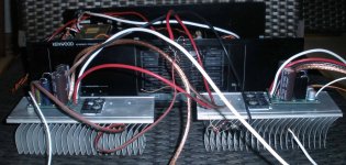
Stuff arrived in the post, things got put together, a few wires were trimmed and some soldering happened. A few small things left to buy, but I'm getting there...
In the pic:
2 x DPS600 45/55
2 x The Wire Amp [one just about ready for testing]
2 x The Wire psu [one hooked up is at +/-20Vdc]
1 x The Wire SE-SE HPA
Paul.
Attachments

woW! i see the first pic.
Good heatsink..is a part of case or you bought separately?
You have already taken the first test? (bias and offset on resistive load).
I'm glad that you have assembled following my advice for dps-600 🙂
Regards
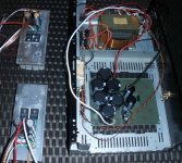
Good heatsink..is a part of case or you bought separately?
You have already taken the first test? (bias and offset on resistive load).
I'm glad that you have assembled following my advice for dps-600 🙂
Regards
Not tested yet, need correct fuses & resistors first.
Heat sink was taken from a Yamaha DSP-E800 amp, the final heatsinks will be bigger...
Is a good layout for the dps-600's, with 10mm gap between units & under the base 🙂
Heat sink was taken from a Yamaha DSP-E800 amp, the final heatsinks will be bigger...
Is a good layout for the dps-600's, with 10mm gap between units & under the base 🙂
Its A Live!
Last day of my holidays is nearly over and it'll back to the tedium of driving an LGV on UK roads tomorrow. With it being a gloomy day out side, today has been a good day for getting stuff done...
First up was the two dps-600's; with everthing in place and me stood 2 meters away from the units and an arms length from the wall socket, I flicked the switch. I'll admit to a little dissatisfaction creaping in, my phone was in hand waiting to record a magnificent explosion, or at least a puff of blue smoke... No, neither of these things occurred, just two green LEDs springing into life and a nice stable 90Vdc showing on the meter...
I was disappointed to see the second unit also firing into life with no more destructive force than the first. Oh well, You Tube fame will have to wait.
Next up on the floor was the first Wire Amp. With as much pomp and circumstance as I could muster whilst lying belly down on the living room floor, and possibly being a little to close for my personal safety. I flicked the switch once more... No bangs, pops, puffs of blue proceeded and a quick inspection for rapidly overheating parts was fruitless. If it weren't for the healthy readings from the meter, the thing could have not been on at all... Ten minutes of swapping wires over and detaching & reattaching amps, the second was ready to go. With breath held and quick flick of the switch, yet another healthy amp comes into the world.
Well it's all going well so far, next will be to try the dps-600's and amps in unison and possibly with an active load. But that's for my next holiday...
😉
Hoping everyone else is doing well.
Paul
would it be better to have it so that 2 identical resistors were used, one in circuit all the time and another switched in in parallel? I presume lower resistance = higher current? this way there is never a time, no matter how short where there is an open circuit this way it could easily be 300 and 600ma, or calculate 200 and 600 easily enough
4. For the bias adjust, I should have been a little more clear. You definitely want the relay to put another resistor in parallel with the existing one to change bias levels. You do not want to change between two different resistors as the amp could behave very poorly if you do this. You can also add a capacitor across the main resistor to slow the change in the bias setpoint.
I have been thinking about this again. I'm a bit slow ....
My reading of the LME49830 datasheet suggests we've got 2mA constant current through the bias circuit, the resulting voltage dropped across the R between these pins sets the bias. Is that correct?
So to be clear what we want really is a resistor between pin 3 and 2 of the bias trimmer position (or a short and use R42 on amp pcb) and a NC relay to a parallel resistor or two. Then decouple at the switched resistor terminals. Also populate C77? With this setup the extra resistors are switched out while normal operation of the circuit.
A low EMI solid state relay could control the parallel resistance and ensure relay operation doesn't adversely impact amp performance.
Hi,
This switch bias can be good for many reason.
In my opinion, it makes no sense to set 300mA-600mA, since with simple switch delay from startup. (another thing is, if you change dynamically), then I think start with 80-100, just for no stress at switch on.
High res= high current bias. (reason becouse is not good change two single res).
it's better that relay close a resistor in parallel at original. (calculate sum of res for low bias)
... notice of Opc? maybe not back from the sea? 🙂
Regards
Last edited:
BuildMeSomething,
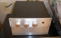
you showed me yours so I will show you mine.
The preamp is OPC's other balenced to single headphone amp. I left out a few parts and made it Se to Se and changed the gain to 3. I used a stepped volume and balance control. The box just underneath is the powersupply, a all fet reguladed supply from ebay.
Just under the power supply is a FM tuner I rescued from the side of the road. A lot of sanding and cleaning and a new paint job. Runs well sounds fine.
The chasis I will be using is a Kenwood KM106 that I got from ebay. One channel was defective so I bought it for $25. Rails are +/-68 volts. The amp was rated at 130 watts/channel and has a led/VU display. New power supply is ready to go. I don't know if I will add a higher supply for the LME chip. I will listen to it and decide later. Both boards have been tested with a bench power supply and initial bias was set to 200ma. The heatsinks are a bit on the small side. The heatsinks are the original from the amp. I have another working Km106 and have run it very hard and it does not get too warm. I will wait and see how warm the amp gets with the LME boards before I turn up the bias any higher.
Boards were tested on junk speaker so I can't tell how they sound.
Attachments
- Home
- Amplifiers
- Solid State
- "The Wire AMP" Class A/AB Power Amplifier based on the LME49830 with Lateral Mosfets