Only very slightly better Roberto,
Do you mean that, in a multi amp system, it is better to power each amp with a separate dedicated power supply?
yes, this independant of psu.
Not have sense a very good amatorial amplifier...with not adeguate psu or criteria.
Multi active way, solve a very big problem of passive crossover, a this point ,all is simple and clean but...why not respect intermodulation point in all? one amp..one psu,this have sense.
Owen, I have to pull back from the transistors purchase, please excuse the inconvenience.
so...2 pairs are available.
so...2 pairs are available.
yes, that was the plan, I planned to buy 2 x dps400 and 2 x dps500 or 600 for active 2 way, but given the generations needed to edit the DPS400 for the high bias level (still not high enough at 400ma, we need 600+ for highest performance) and no mention at all of the high priced regulated PSUs, i'm not willing to do this without results to show me it will work, so I dont know what to do. I do not intend to be a paying beta tester, even if support is good, I am on the other side of the world, sending back and forth is not an optionyes, this independant of psu.
Not have sense a very good amatorial amplifier...with not adeguate psu or criteria.
Multi active way, solve a very big problem of passive crossover, a this point ,all is simple and clean but...why not respect intermodulation point in all? one amp..one psu,this have sense.
Last edited:
yes, that was the plan, I planned to buy 2 x dps400 and 2 x dps500 or 600 for active 2 way, but given the generations needed to edit the DPS400 for the high bias level (still not high enough at 400ma, we need 600+ for highest performance) and no mention at all of the high priced regulated PSUs, i'm not willing to do this without results to show me it will work, so I dont know what to do. I do not intend to be a paying beta tester, even if support is good, I am on the other side of the world, sending back and forth is not an option
Qusp Certainly, we are in tune then. However, please do not take my explanation as a conviction or forced to buy these SMPS.
DPS-400: interventions are limited to the startup phase, not at the core of the SMPS, in fact, Owen has always said that increasing the bias current after the DPS-400 is started, it keeps the bias and good works correctly even in power .
I mean, if I was not sure of the product, I would not have lost even a single minute. This SMPS was developed in 2005, for class D commercial and is currently used in some measuring instruments with small changes. problems do not know about this product.
Unfortunately we do not know. if a product is not perfect, I have no reason to produce it. sorry for this, heheh, it's my truth.
For issue on shunt down(without remote ctl), this is my stupid error while solve current startup, not think That put a resistor on high voltage capacitor, then voltage decrease with very long time hahaha!
Obvius that original version is perfect for D class,also used in multi way very quiet.
However, it will soon be proven correct operation with 400mA of bias also.
regards
Last edited:
hey not questioning you mate, but its a difficult leap to make with no info. yes increasing the bias after start is possible thats true he has always said thats possible, but how to do this in an automated fashion with the case on? is that possible via software/i2c control?
yes its true the 400 seems a good supply and with the bias thing sorted out and clean shutdown i'm probbaly going to get some, but its not the one i'm really interested in and i'm lacking info on the 500 and 600, I mean was there the same problem with 500-600? is there a fix? was a solution even pursued? its the 500 and 600 that ive been interested in from the start; I want a regulated PSU for the mid-woofers and if its not a switching PSU, it'll be a linear regulated PSU.
yes its true the 400 seems a good supply and with the bias thing sorted out and clean shutdown i'm probbaly going to get some, but its not the one i'm really interested in and i'm lacking info on the 500 and 600, I mean was there the same problem with 500-600? is there a fix? was a solution even pursued? its the 500 and 600 that ive been interested in from the start; I want a regulated PSU for the mid-woofers and if its not a switching PSU, it'll be a linear regulated PSU.
Last edited:
AP2,
Please do not be discouraged by the rants, to me they shows questionable manners. I do appreciate your effort to offer the diy community a customized smps power supply. There are too few manufactures to be so generous to the DIY audio community, it would be a shame to run them off. Please continue you efforts and if successful I would like to opportunity to purchase if affordable and available.
Bill
Last edited:
Yes, just a few words, maybe it can be interesting.
as I use in some class D, also for safety reasons, you can add a simple circuit that (automatically or under control) increases the bias. eg. start at 50mA and go to 600mA (if no error).
command can be done through an optocoupler.
I need the scheme of the amplifier to see how to do it, perhaps this idea may also like to Owen. 🙂
Independant of smps limit, it can be a good innovation eheh!
hey not questioning you mate, but its a difficult leap to make with no info. yes increasing the bias after start is possible thats true he has always said thats possible, but how to do this in an automated fashion with the case on? is that possible via software/i2c control?
yes its true the 400 seems a good supply and with the bias thing sorted out and clean shutdown i'm probbaly going to get some, but its not the one i'm really interested in and i'm lacking info on the 500 and 600, I mean was there the same problem with 500-600? is there a fix? was a solution even pursued? its the 500 and 600 that ive been interested in from the start; I want a regulated PSU for the mid-woofers and if its not a switching PSU, it'll be a linear regulated PSU.
I think that pdf of dps-500 explain well, special parts and circuit used, just it is developed around audio amplifier. i not think have problem on current startup (i know it is used for ab professional mono-block also).
dps-600, Owen have one, maybe have just low power DC (+/-62V).
has been nearly two years since the first DPS-500 sold, I never knew that someone had called AP for breaking problems or noise or other.
when i develop this smps, first reason is just solve some aspect of the dynamics of the sound, on which I have continued to some studies, in particular on the geometry of the envelope sound. but this is other story.
Last edited:
Im posting from mobile phone so can't find the posts easily but I thought opc had posted measurements of the amps performance far earlier in the thread, I was reasonably confident these were with linear psu, any reason these aren't useful to compare to smps measurements posted recently?
AP2: the schematic is on the first page of the thread, think there was a single routing change as there was an error in the mosfet pinout, not sure if Owen has gone back and edited the first post or not.
that being said, part of the appeal of these supplies are they are supposed to be plug and play. I think I remember now what happened with the 500 and 600, there was no 120v version, so opc could only test at work. hmm how can I be assured it will work with the high bias? much as I admire the bleeding edge, I dont really want to be sending PSUs back and forth; I dont have the measuring kit up to the job of diagnosing problems either.
edit: just saw your post. OK but presumably you didnt think there would be a problem with the 400 either. what we are talking about here is closer to a class A amp than a normal class AB, with higher bias. its a difficult position to be in, I have already posted in the thread that I admired the supplies and I am very interested, but given the problems with the 400 (now sorted out mostly) it puts doubt in my mind, it wouldnt be a small amount of money for the order of 4 supplies + shipping and given the 600 and 500 were given top billing as world beaters, but now they dont get a mention it doesnt help.
I think i'll email you though Roberto, I dont want my posts misconstrued as a rant, that is not the case, i;ve already defended you more than once in here, but these are real concerns and close to $700 in power supplies when I already have all the parts for linear supplies.
Last edited:
Ok for scheme, later i add this circuit and show...just for curiosity.AP2: the schematic is on the first page of the thread, think there was a single routing change as there was an error in the mosfet pinout, not sure if Owen has gone back and edited the first post or not.
that being said, part of the appeal of these supplies are they are supposed to be plug and play. I think I remember now what happened with the 500 and 600, there was no 120v version, so opc could only test at work. hmm how can I be assured it will work with the high bias? much as I admire the bleeding edge, I dont really want to be sending PSUs back and forth; I dont have the measuring kit up to the job of diagnosing problems either.
high bias, 600mA you mean? i can try in laboratory but i not have doubt on dps-500,know well up to extreme test.
dps-600 not running at 110Vac, for test with high bias, i think Owen can do it.
this high bias on A-B class is not small thing, I'd be curious to see how other SMPS, even with simple fft. just for understand. not only as strees.
To Qusp:
I saw that you have defended me from the attacks of ignorant. but now I do not understand what the problem is, DPS-500 is ready without modification, I am sure that is a feeder to the top available at this time, not only in audio measurements, but also listening immediately.
This is a top-of AudioPower much unreachable by other companies, especially for special parties that use, in your case is perfect (I mean technically). no one would dream of touching it to change something in this SMPS, me neither.
Hi Guys,
I've got a few more measurements to post up that I took today.
I measured the startup and shutdown behaviour of the DPS-400 and I re-did all the measurements for the DPS-600 since I had somehow misplaced the folder.
I'll start here with the current DPS-400 startup and shutdown behaviour.
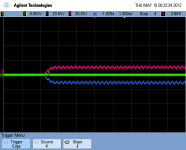
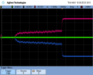
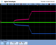
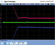
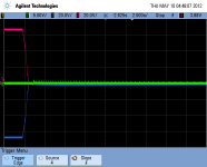
In the scope captures, red is the + supply, blue is the - supply and green is the output. Note that the V/div scale is different for the output and the supplies to better show any voltage deflection on the output.
1. Failed startup at 400mA - plugging unit in fully discharged
2. Successful startup at 300mA - plugging unit in fully discharged
3. Successful startup at 400mA - Unit already plugged in, power SW used
4. Shutdown using switch @ 400mA
5. Shutdown using switch @ 400mA zoom in
6. Shutdown @ 400mA by unplugging unit
As a side note, I would indeed agree with Bill that the aggressive and rude posts are really not in very good taste. Everybody makes mistakes, and if you want a fully polished product with a warranty that has been thoroughly tested and verified then I'm afraid DIY audio is probably not the hobby for you.
Although I completely agree that these issues need to be fixed before the supply is suitable, I think going about it in a civil manner is more constructive than launching a full on attack against someone.
Let's give AP2 the benefit of the doubt and see if his fix works for us. Please try to keep in mind that he doesn't owe any of us anything, and he could just as easily shoot us all the bird and walk away. How about we drop the sense of entitlement and pick up the teamwork flag instead.
Regards,
Owen
I've got a few more measurements to post up that I took today.
I measured the startup and shutdown behaviour of the DPS-400 and I re-did all the measurements for the DPS-600 since I had somehow misplaced the folder.
I'll start here with the current DPS-400 startup and shutdown behaviour.
In the scope captures, red is the + supply, blue is the - supply and green is the output. Note that the V/div scale is different for the output and the supplies to better show any voltage deflection on the output.
1. Failed startup at 400mA - plugging unit in fully discharged
2. Successful startup at 300mA - plugging unit in fully discharged
3. Successful startup at 400mA - Unit already plugged in, power SW used
4. Shutdown using switch @ 400mA
5. Shutdown using switch @ 400mA zoom in
6. Shutdown @ 400mA by unplugging unit
As a side note, I would indeed agree with Bill that the aggressive and rude posts are really not in very good taste. Everybody makes mistakes, and if you want a fully polished product with a warranty that has been thoroughly tested and verified then I'm afraid DIY audio is probably not the hobby for you.
Although I completely agree that these issues need to be fixed before the supply is suitable, I think going about it in a civil manner is more constructive than launching a full on attack against someone.
Let's give AP2 the benefit of the doubt and see if his fix works for us. Please try to keep in mind that he doesn't owe any of us anything, and he could just as easily shoot us all the bird and walk away. How about we drop the sense of entitlement and pick up the teamwork flag instead.
Regards,
Owen
Attachments


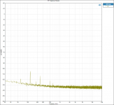
Next up are the results from the DPS600. Here are the test conditions:
Amp setup = SE
PSU = DPS600
+/- 67VDC on Mosfets
+/- 84VDC on LME
Bias level = 400mA (some 600mA - noted)
Gain = 28dB
Input = 200mV RMS
Output = 3W
Load = 8 ohms
Amp setup = SE
PSU = DPS600
+/- 67VDC on Mosfets
+/- 84VDC on LME
Bias level = 400mA (some 600mA - noted)
Gain = 28dB
Input = 200mV RMS
Output = 3W
Load = 8 ohms
Attachments
-
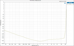 THD+N Ratio vs Measured Level.png82.3 KB · Views: 218
 -
 THD+N Ratio 3W 8R 400mA.png62.1 KB · Views: 163
 -
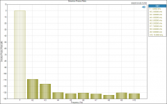 Distortion Product Ratio 3W 600mA.png47.3 KB · Views: 181
 -
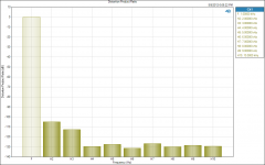 Distortion Product Ratio 3W 400mA.png47.3 KB · Views: 205
 -
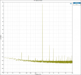 FFT Spectrum Monitor - 3W 8R 400mA.png101.3 KB · Views: 189
 -
 FFT Input Tied to GND.png96.8 KB · Views: 203
 -
 FFT Input Connected to AP.png97.3 KB · Views: 213
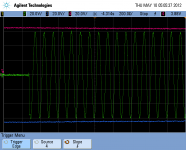
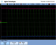
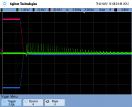
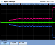
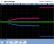
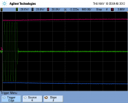
To go along with those I've got the startup and shutdown behaviour as well as the rail's reaction to full power bursts which helps show the performance of the supply's regulation.
1. Supply Startup - 400mA - fully discharged, plug-in
2. As above, but zoomed in
3. Supply Shutdown - 400mA - unplugged
4. As above, but zoomed in
5. 1kHz full power transients (225W)
6. 1kHz full power transients (225W) zoomed-in
7. 10kHz full power transients (225W) zoomed-in - start of transient
8. 10kHz full power transients (225W) zoomed-in - end of transient
Attachments
-
 Full Power Pulse Zoom 10K START.png61.3 KB · Views: 165
 -
 Full Power Pulse Zoom 1K.png69 KB · Views: 178
 -
 Full Power Pulse.png134.8 KB · Views: 265
 -
 Shutdown - 400mA - zoom.png64.9 KB · Views: 148
 -
 Shut Down - unplug - 400mA - longer.png55.8 KB · Views: 138
 -
 Startup - 400mA - zoom.png91.1 KB · Views: 133
 -
 Startup - 400mA.png77.2 KB · Views: 183
 -
 Full Power Pulse Zoom 10K STOP.png49.8 KB · Views: 162
Thanks Owen, very good setup on measure. i are happy when see burst zoomed with this smps,becouse without capacitors at output, see what is fast regulation,feedback and other.
with respect, some not have adequate knowledge to understand, looking at the modulation on the supply rails, which follows perfectly up to 10Khz. this would be sufficient compared with a linear transformer (this same measure), then it is simple even for those who do not have a profound preparation.
(67V to consider that we are almost out of range limit of the controller) I sent this version has the optimum range at 62-63V
Last edited:
impressive dynamic performance indeed!!. pic 4 above is a worry, but 5-8 seem to make it worth chasing down the issue. i'm not sure I quite get the scale other than referenced to full rails, but that doesnt tell me how much the output is scaled given its different? divisions on rails and output? (talking dps600 here) I wont comment on the dps400 unplugged, thats pretty scary, but I gather this is before the mod?
but a quick note I wrote before
Owen thanks for that; absolutely lets see what can be done, please do keep in mind that this is a bit of a different situation to the normal DIY purchase as AP2 mentions. there is no schematic and its a topology that most of us are pretty unfamiliar with, with issues that can easily happen outside the bandwidth of your average scope (assuming you have one), so diyer or not; understanding, monitoring or fixing problems on our own is not a reasonable expectation IMO and we just saw AP2 say he wouldnt attempt it himself. under these circumstances and given they are powering a DC coupled amp, I think it is perfectly reasonable to expect that obvious issues are sorted out and some assurance of performance is given. Rudeness and name calling is another thing entirely.
@AP2 600ma tall order? well see thats the thing, those coming from a class A world will often talk of 2A and higher bias (ok sometimes). will they do that from a cold start without sag? no they wont, but there is also no mechanism to latch up and cause transients like we have in the above pics.
so what can we do, seems a softstart is needed, could a fault condition be catered for by some sort of super capacitor to supply the PSU long enough that even if the cord is yanked, death is a bit more graceful? see i'm already looking to scatter sensors around this monitor system and connected builds with wireless Xbee modules and i'm looking for this to be battery powered for similar, but less extreme reasons.
I do appreciate your openness to this AP2, i've said that before all this and my thoughts have not changed
Last edited:
ok I got it now, right so we are looking at about 1v div on the output transient yes? thats not so bad as I thought for the dps600. the dps400 though is still a bit of a concern
(spike are 200mV) Hmm .. I'm looking at pic 2 (start sequence) and I see that the amplifier (output) is affected by the voltage remains at 20V before going up. then the problem of switching off, really tried here goes. amplifiers have a small instability if the voltage is still low. now is to see if because of the voltage for the driver.
i mean, amplifier not show this defect, if the voltage rises rapidly. heheh, this is a beautiful study, we investigate now 🙂
well, the proof is right in pic 4. for safety, stop the trace output (green), i want se red or blue voltage actions in this segment zoomed. very help,if you can show ch1 on one rail of lme also
Last edited:
- Home
- Amplifiers
- Solid State
- "The Wire AMP" Class A/AB Power Amplifier based on the LME49830 with Lateral Mosfets