Owen,
in the beginning you proposed a transformer-"We could ask for custom transformer that was say 60-50-0-50-60 @ 0.1A-7A-0-7A-0.1A with both 120 and 240V primary windings and that would work for everyone that wanted about 300W into 8 ohms". I assume this is for one mono block, if I wanted to make a stereo would you recommend doubling that size? As far as power supply most of mine have been CRC for class A amps, is there any significant change in power supply design for class AB amp? I have used the BrianGT power supply boards at chipamp.com for my class A amps would they be suitable for this project? It is built with 4 mur1560 diodes 2caps resisters and 4 more caps.
Bill
I suggest you change the current rating of the middle windings from 7Aac to, 9Aac to 10Aac.
This gives you 900VA to 1kVA for a 300+300W amplifier.
This gives you 900VA to 1kVA for a 300+300W amplifier.
Hi,
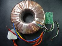
I will add an additional small transformer with dual low voltage/ampere windings. Each winding will be in series with each winding on the main transformer and then regulators.
Another solution could be two voltage doublers and regulation after that (ex. NAD 214/216).
I will add an additional small transformer with dual low voltage/ampere windings. Each winding will be in series with each winding on the main transformer and then regulators.
Another solution could be two voltage doublers and regulation after that (ex. NAD 214/216).
Hi,
I will add an additional small transformer with dual low voltage/ampere windings. Each winding will be in series with each winding on the main transformer and then regulators.
(ex. NAD 214/216).
I will be using the additional small transformer approach as well. This works well as long as the regulation is relative to main PS ground.
Here is a question for the group: What would happen if the LME PS regulation were relative to "quiet ground" instead of main PS ground?
Last edited:
A better way, if you're buying a toroid and it's not potted, is to simply add some windings of your own.
Eg, if it's 2 turns per volt and you want ± 12V extra. Then do two windings of about 6 turns. You'll have to measure it.
That's how all of ours have been made. 0.56mm diameter enamelled copper wire was used.
I'd suggest to pay attention to amount of extra volts though to allow not just to clear the output stage and the regulators minimum overhead but also for the mains to swing, or if you one day might want to sell the amps to someone with a much higher or lower mains voltage than yours typically is.
On one Hafler DH200 I modified, I added an early stage, done with this method of a replacement toroid with extra windings joined to the main windings and to their own bridge and following main res caps then regs, the early stage earth was about +5V DC from the main earth star and centre tap. I ran a thin wire between the early stage regs earth and the main earth to equalise the voltage.
Last edited:
.......... if it's 2 turns per volt and you want ± 12V extra. Then do two windings of about 24 turns each. ............
🙂 Yes, I added at 2 volts per turn
I was distracted and only had time for a hew hours sleep last night Thanks for the correction. I do now recall seeing what looked like about 20 to 30 turns on them. Of course it will vary with the size of the transformer.
I was distracted and only had time for a hew hours sleep last night
Thanks for the correction. I do now recall seeing what looked like about 20 to 30 turns on them. Of course it will vary with the size of the transformer.
Last edited:
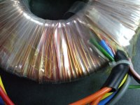
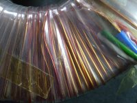
On this 1kVA transformer you can perhaps make out the extra windings all within a couple of inches.
They did them in two different enamel colours.
They did them in two different enamel colours.
Attachments
Last edited:
On this 1kVA transformer you can perhaps make out the extra windings all within a couple of inches.
They did them in two different enamel colours.
That is very ingenious. So you connect wires in series with the secondaries, give it a few turns and the original center tap is also the center tap for the new secondaries?
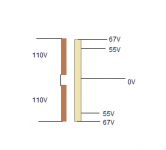
Yes. If connected this way, just like having taps for, eg, 92 - 80 - 0 - 80 - 92.
The 80's go to a big bridge, the 92's to a small one. Then the two earth's formed from the low and the high voltage capacitors are wired together.
....edit: I just read AP2's post which says the same.
The 80's go to a big bridge, the 92's to a small one. Then the two earth's formed from the low and the high voltage capacitors are wired together.
....edit: I just read AP2's post which says the same.
Last edited:
yes, all used in a commercial low cost since long time.
problem is, that link keep full ripple from power link, (eg. your 80V), for this i advice use good regulator for 92V. but this need 10V higher than of voltage you need.
problem is, that link keep full ripple from power link, (eg. your 80V), for this i advice use good regulator for 92V. but this need 10V higher than of voltage you need.
I used to use 7815 and 7915. Fitted two, eg, 33V (ish), Zeners in series from the ground pin to the ground to 'pedestal' the regulator. The Zeners shift when warm, so after an initial build and power up and let the settle, I measure the voltage drop across them all then usually taken them off and swap them to make matching ± voltages. Laborious. I think I'd do it with the 317 and 337 next time. Or maybe try out the SuperTeddy Power Reg or a simple discrete transistors design.
- Home
- Amplifiers
- Solid State
- "The Wire AMP" Class A/AB Power Amplifier based on the LME49830 with Lateral Mosfets