And also to me the instructions are not ambiguous:
"Populating the Board:
It is best to start with all the SMD parts on the board before soldering any of the larger parts. I like to start on the bottom of the board, soldering all the SMD parts, then flipping the board over, mounting the standoffs, and soldering all the top SMD parts.
......proceed to mount all the through-hole parts on the board. It’s a good idea to solder in the + output lead before mounting the heatsink and caps....."
Owen fitted the heatink nearly last.
Owen, this part was showing as 'not stocked' at both Digiky and Mouser: 12pF 100V 1% part is suggested (08051K120FBTTR). I found a 10pF Accu-P 100V 1% 0805 that is there though: Mouser part no: 581-08051J100FBT
In the schematic, when clicking on the gate resistors, it says both 51Ω and 220Ω or 330Ω. This might cause some confusion and some questions for you.
Have you tested this with a reactive load and found that under all conditions there is no requirement of an output Zoebel or inductor? Very good if so, as in my limited experience the coil often has a bad effect on the sound.
Cheers,
Ian
Last edited:
my god you are right, I dont know why, but I think the step saying 'last thing to do is check continuity between the v pin and the heatsink' threw me and confused by that or not, then from that point on i think i read what i expected to see. even reading it last night to double check before posting. that and i didnt use the desk to find the bottom of the pcb for the lme i used my finger, partially because i wanted to have definite contact between the pins and the edges of the through holes by pressing them against it with the solder tip, rather than floating in a plug of solder and partly because i found wiggling the part in on the heatsink frustrating and the pins not all exactly level by the time i was done.
Ian, i know the next paragraph says solder the smd parts first and thats intuitive, but that was after the first step in my mind at the time; clearly broken
so my apologies opc, in the light of day the manual is fine, my head.... hmmm. i would suggest a simple phrase, 'set that aside' because its not mentioned again after the fitting. its logical but i dont think i was in logic mode after the lme fitting, i used keratherm too though, maybe the adhesive makes that step much easier.
HYPERTUNE: actually the second one was not as hard, there was no going back after they were soldered, i didnt trust the heat of desoldering. its only those 2 caps that are really difficult, the resistors are no problem. i used some long standoffs mounted on top for soldering the underside parts on the second board.
Last edited:
I guess opc read my reply and used the mantra 'if you cant say something nice, say nothing at all' amazing restraint on his part.
All these posts and no pics ... cmon qusp!
Its actually handy, in a sadistic kind of way, that you've done it "the hard way" up front (intentional or otherwise). Now all the rest of us hopefully don't make the same mistake and get ourselves in over our head! 😀
Its actually handy, in a sadistic kind of way, that you've done it "the hard way" up front (intentional or otherwise). Now all the rest of us hopefully don't make the same mistake and get ourselves in over our head! 😀
Last edited:
not really much to see yet, as i dont have a lot of output wiring to waste, so until i've done a test fit in the enclosure i'm not soldering the main caps. plus i'm waiting for someone to post a build thread and its not going to be me.
IanAS: there are 0805 12pf/100V accu-P at mouser, they actually have a better range than DK, but more expensive. me, i'm in contact with cornell dublier (CDE) to get some of their smd PTFE shielded RF caps in 20pf, in the meantime i'll stick with the mica supplied
IanAS: there are 0805 12pf/100V accu-P at mouser, they actually have a better range than DK, but more expensive. me, i'm in contact with cornell dublier (CDE) to get some of their smd PTFE shielded RF caps in 20pf, in the meantime i'll stick with the mica supplied
Last edited:
I've ordered and paid for a complete set of PCBs but after the delays my project requirements have changed and I think I'd rather go class D now. There seems to be many people wanting PCBs, would someone like to take my order? I've messaged Owen but no reply. No worries if not though, I could just resell it when it finally arrives 🙂
by popular demand (ok hochopeper)
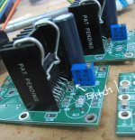
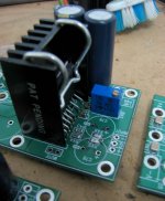
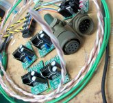
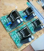
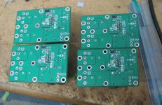
so the first pic was the one i struggled with and ended up with that wonky cap, second one i managed ok after some more swearing and the others without the pots (which i wasnt silly enough to install as well before the caps) are the 2 i did correctly and are thus neater.
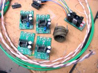
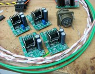
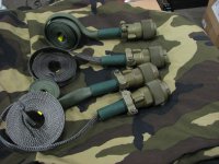
so all are setup for balanced DC coupled input and standard gain; i'm paused till i install in the chassis as i dont want to waste any of the rather chunky and excellent VHAUDIO copper in PTFE output wiring also in the pic the awesome OTT ITT Cannon Milspec connectors i'm using for the multicore speaker cables.
so the first pic was the one i struggled with and ended up with that wonky cap, second one i managed ok after some more swearing and the others without the pots (which i wasnt silly enough to install as well before the caps) are the 2 i did correctly and are thus neater.
so all are setup for balanced DC coupled input and standard gain; i'm paused till i install in the chassis as i dont want to waste any of the rather chunky and excellent VHAUDIO copper in PTFE output wiring
also in the pic the awesome OTT ITT Cannon Milspec connectors i'm using for the multicore speaker cables.Attachments
-
 lateral wire part way there_28Feb2012_0615.jpg213.8 KB · Views: 997
 -
 lateral wire part way there_28Feb2012_0616.jpg157.9 KB · Views: 965
 -
 lateral wire part way there_28Feb2012_0619.jpg253.8 KB · Views: 954
 -
 lateral wire part way there_28Feb2012_0620.jpg246.1 KB · Views: 922
 -
 lateral wire part way there_28Feb2012_0621.jpg276.3 KB · Views: 899
 -
 lateral wire part way there_28Feb2012_0608.jpg194.5 KB · Views: 451
 -
 lateral wire part way there_28Feb2012_0602.jpg177.3 KB · Views: 411
Last edited:
I'm sure that cap will add a corresponding curve to the frequency response. You are the only one to blame. Owen likes things nice a straight. You should really follow the guide lines and you will have a flat frequency response!
Hey I missed seeing this post qusp ... nice work!
Hopefully the mosfets start rolling out of the factory and this thread is flooded with pics soon! 😀
Hopefully the mosfets start rolling out of the factory and this thread is flooded with pics soon! 😀
I'm sure that cap will add a corresponding curve to the frequency response. You are the only one to blame. Owen likes things nice a straight. You should really follow the guide lines and you will have a flat frequency response!
I know 😱 and surely the extra tin/copper/lead/silver in the signal path will produce such a vile colour to the sound to that i will want to blow my brains out!!
i shall turn this emoticon in on myself

it wasnt so much the result, as you can see i actually managed ok with that (although it does bug me a bit that its there), but the journey (my own doing) was infuriating
Last edited:
thanks AP2, i'm sure it'll fit nicely with your PSUs, which i'm almost certainly going to get, i talk myself into it more and more each day i just need to put the coin aside.
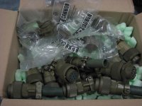
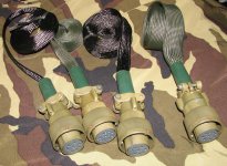
the cannons are indeed awesome connectors, i scored them here on the forum for a song; at farnell/element14 that single connector and panel mount pair would be almost 200 dollars and this box full of them..... nobody else seemed interested in them, or perhaps didnt know what they were, so lets say i did better than OK on the deal; I love this forum sometimes. they will be used for power umbilicals, speaker cables and even a joke balanced IEM/headphone cable 😀
the contacts are rated for 22A each at 2kV+
a little bit phallic =) but hey. shown below with matching carbon fibre or even their traditional milspec nomex sleeving.
Attachments
At least you have a good sense of humor!
And as for sound of course it makes zippo difference. Had to throw in kindly jab.
Looks great and that cap adds character.
And as for sound of course it makes zippo difference. Had to throw in kindly jab.
Looks great and that cap adds character.
yeah its the best way to cope with failure hehe. I realize its meaningless to the sound, but it doesnt sit well with my OCD.
You gotta have a bit of fun with this DIY stuff to make it individual IMO; thus the OTT connectors, whats the point in using your time and in many cases more cost (when the time is taken into account) than almost equivalent commercial gear, just to end up with something that could BE a piece of commercial high end gear? thats the way i see it anyway.
You gotta have a bit of fun with this DIY stuff to make it individual IMO; thus the OTT connectors, whats the point in using your time and in many cases more cost (when the time is taken into account) than almost equivalent commercial gear, just to end up with something that could BE a piece of commercial high end gear? thats the way i see it anyway.
thanks AP2, i'm sure it'll fit nicely with your PSUs, which i'm almost certainly going to get, i talk myself into it more and more each day i just need to put the coin aside.
the cannons are indeed awesome connectors, i scored them here on the forum for a song; at farnell/element14 that single connector and panel mount pair would be almost 200 dollars and this box full of them..... nobody else seemed interested in them, or perhaps didnt know what they were, so lets say i did better than OK on the deal; I love this forum sometimes. they will be used for power umbilicals, speaker cables and even a joke balanced IEM/headphone cable 😀
the contacts are rated for 22A each at 2kV+
a little bit phallic =) but hey. shown below with matching carbon fibre or even their traditional milspec nomex sleeving.
Hi,
woW! I have a passion for military equipment...i know well, I worked in the laboratories of Aeronautics and later I also designed some circuits. was a strong and beautiful experience working with brands really special. really very beautiful.🙂
Perhaps you also have military experience? hehe! .. what is.. the camouflage tissue under connectors? 😀
I'm happy if you use DPS-600/500, you can feel a real difference in the dynamics of sound. This is not easy to disclose in words, especially in a world of.. blah .. blah , all good..all nice..
Regards
Just wondered opc (this isn't to do with the shortage or anything) where have you purchased the FETs for this I can't seem to find a distributor anywhere nor the manufacturer. I ask because I think I want to try to use them more in amps.
Btw if you can I'm happy to get an answer from anyone!
Btw if you can I'm happy to get an answer from anyone!
huh? its been discussed at length that the fets are alfet, manufactured by semelab. they come under many names, you'll pay quite a bit more than the price the gb paid. you can get them at farnell/element14, but $$$
And to think that you question the use of good Australian tax dollars spent in the military?
Look at the payback!
Super premium subsidized audiophile grade connectors!
If only we had such great forethought in Canada, wait a minute we do.
Look at the payback!
Super premium subsidized audiophile grade connectors!
If only we had such great forethought in Canada, wait a minute we do.
Hi Boscoe,
I purchased mine from RichardsonRFPD. There are a number of places that sell at least one of the many different variations of these parts. For smaller orders you might want to try here:
Lateral Mosfet
They are out of stock now, but told me they would get more sometime in April. It's the best pricing I've been able to find on smaller quantities.
Cheers,
Owen
- Home
- Amplifiers
- Solid State
- "The Wire AMP" Class A/AB Power Amplifier based on the LME49830 with Lateral Mosfets