Check my pic for the wire that goes from - on the PSU input to a - input terminal.
Last edited:
Check my pic for the wire that goes from - on the PSU input to a - input terminal.
Ah yes, I see that now. Thanks. It is clear to me what I need to do.
St By also has the GND if you like it on that side, I guess.
Even better. 😎
The /STBY pin closest to the LED output is ground.
When I designed this card I figured that the amp and the source would have a decent common ground, so a full differential input would be OK. Then everyone started using laptop adapters with 2 pin power plugs, portable media players, etc... yup, fail.
Next board rev will have ground pins by the inputs so you can strap them together right there. However I have to get rid of 50+ existing PCBs first 🙂
Can anyone recommend a barrel power connector which is 7.4 X 5.08mm? I cannot seem to find any on Digikey or Mouser. If not I guess I will have to use a adapter (http://www.amazon.com/BiXPower-X75-Connector-Converter-5-08mm/dp/B00NUG5RWC). I plan to use the Dell laptop brick (model: DA130PE1-00). The brick portion has a 3prong input so going into the brick it seems to have a ground not sure if it has a ground on the other end. Is there a way to find out if it does or not?
or recommend a good linear power supply that I can use that does not cost arm and a leg 🙂. The other option is to pickup the mean well that GMarsh posted couple of days ago.
or recommend a good linear power supply that I can use that does not cost arm and a leg 🙂. The other option is to pickup the mean well that GMarsh posted couple of days ago.
Last edited:
The /STBY pin closest to the LED output is ground.
When I designed this card I figured that the amp and the source would have a decent common ground, so a full differential input would be OK. Then everyone started using laptop adapters with 2 pin power plugs, portable media players, etc... yup, fail.
Next board rev will have ground pins by the inputs so you can strap them together right there. However I have to get rid of 50+ existing PCBs first 🙂
The next group buy round should take care of that.
I strapped the SBY ground pin to the common ground of the input RCAs. Dead quiet. My one little niggle with this amp is now history.
Thanks all!
Can anyone recommend a barrel power connector which is 7.4 X 5.08mm? I cannot seem to find any on Digikey or Mouser. If not I guess I will have to use a adapter (http://www.amazon.com/BiXPower-X75-Connector-Converter-5-08mm/dp/B00NUG5RWC). I plan to use the Dell laptop brick (model: DA130PE1-00). The brick portion has a 3prong input so going into the brick it seems to have a ground not sure if it has a ground on the other end. Is there a way to find out if it does or not?
or recommend a good linear power supply that I can use that does not cost arm and a leg 🙂. The other option is to pickup the mean well that GMarsh posted couple of days ago.
A linear supply is really simple to build. There are certainly better supplies than the one I built, but it sounds excellent and I like it better then my SMPS.
I've got that exact laptop adapter, DC output barrel is connected to AC ground.Can anyone recommend a barrel power connector which is 7.4 X 5.08mm? I cannot seem to find any on Digikey or Mouser. If not I guess I will have to use a adapter (http://www.amazon.com/BiXPower-X75-Connector-Converter-5-08mm/dp/B00NUG5RWC). I plan to use the Dell laptop brick (model: DA130PE1-00). The brick portion has a 3prong input so going into the brick it seems to have a ground not sure if it has a ground on the other end. Is there a way to find out if it does or not?
or recommend a good linear power supply that I can use that does not cost arm and a leg 🙂. The other option is to pickup the mean well that GMarsh posted couple of days ago.
I'd just use that adapter, or alternatively just hack the end off the Dell adapter if you don't plan on using it with a laptop again.
I've got that exact laptop adapter, DC output barrel is connected to AC ground.
I'd just use that adapter, or alternatively just hack the end off the Dell adapter if you don't plan on using it with a laptop again.
No plans to use it with a laptop again. Will order the adapter. Any pictures on how you have the barrel connector wired to be used directly with the brick and adapter?
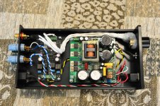
Here's some "amp porn" for those of you who are into it. I finished this up last weekend, haven't had a lot of time to do any detailed listening yet, but initial impressions are extremely good. I guess I do need to jumper one of the - inputs to ground, as I have some hum coming through. Interesting thing with the hum: I'm using a stepped attenuator for volume control. The hum is barely present with the pot at max resistance (50k), gets louder with increasing volume (i.e. decreasing resistance), then totally goes away when the pot is completely open. Initially I didn't notice the hum (see earlier post) because I didn't have the pot wired in, and was using my DAC for volume control.
Anyway, a rundown of the build details for anyone who's interested:
Note my lovely glob of hot-melt glue on the attenuator. In my infinite wisdom, I neglected to consider how the pot is mated to the chassis when I soldered up the wires. So the wiring protrudes from the front of the pot, making it not sit nice and flush with the chassis. I had also applied a big blob of hot melt glue to the wiring before I realized this. So I spent time building up a "frame" with more hot melt to make the volume pot mate evenly to the chassis. It's ugly, I know. And after all that, the threaded part of the pot's shaft barely comes through the hole, so the nut holding it in place is probably one light tap away from falling off. Oh well.
Anyway, a rundown of the build details for anyone who's interested:
- PSU: Connex SMPS300RS, customized to 20V output
- Pot: Ebay "DACT Type 21 Stepped Attenuator Potentiometer 50K" from seller lasercollection (current link). Learned about this from the "lunch money amp" thread.
- Chassis: Ebay "1306A full Aluminum Enclosure case/Power amplifier box/DIY chassis -sn" from seller sep_store (current link). Came with all holes (except for the LED) pre-drilled, which was nice. Though the speaker binding post holes were a wacky size, either too big or too small. I had to grind on them a bit with my deburring tool.
- Shielded wire for inputs, I bought that years ago from "John's Wire Shop" on ebay.
- Rest of the hook-up wire, RCAs, binding posts, and on/off switch came from Apex Jr.
- LED and it's current limiting resistor, PCB standoffs, and thermal pad all came from Digi-Key.
Note my lovely glob of hot-melt glue on the attenuator. In my infinite wisdom, I neglected to consider how the pot is mated to the chassis when I soldered up the wires. So the wiring protrudes from the front of the pot, making it not sit nice and flush with the chassis. I had also applied a big blob of hot melt glue to the wiring before I realized this. So I spent time building up a "frame" with more hot melt to make the volume pot mate evenly to the chassis. It's ugly, I know. And after all that, the threaded part of the pot's shaft barely comes through the hole, so the nut holding it in place is probably one light tap away from falling off. Oh well.
Attachments
Somehow I knew people would have noise issues cause of the - input signal not beeing connected to ground. Thats why I wrote such I detailed description on how I connected my system up. Besides, nobody want's to take any chances with their "golden" amp🙂 I would also STRONGLY recommend starting the amp in 500kHz mode since that sounds far better than the stock mode it comes in. Just my 2 cents..
Well added noise for some as default option was a design choice, added noise for all might be a mistake, but easy fixed. Popular 50k pot with tpa3116 has been mentioned too. Not ideal with other tpa3116 ampboards, even worse choice with this ampboard.
Somehow I knew people would have noise issues cause of the - input signal not beeing connected to ground. Thats why I wrote such I detailed description on how I connected my system up. Besides, nobody want's to take any chances with their "golden" amp🙂 I would also STRONGLY recommend starting the amp in 500kHz mode since that sounds far better than the stock mode it comes in. Just my 2 cents..
I should have been paying more attention to your connection setup.
I agree about 500kHz.
Could someone explain the switch settings for AMx? Specifically, which is hi and which is lo? Is the 1 setting high or is the 0 low? The switch itself is marked with one side being "on" but the corresponding silk screened number on the pcb is 0.
Could someone explain the switch settings for AMx? Specifically, which is hi and which is lo? Is the 1 setting high or is the 0 low? The switch itself is marked with one side being "on" but the corresponding silk screened number on the pcb is 0.
This confused me, too. Go by the PCB markings. 0 is low.
matt_garman, i really miss proper case grounding for life saving reasons?!
I'm not sure I follow you, can you elaborate?
The case itself is common withe the mains ground. The mains input on the SMPS board has three pins (earth, live, neutral). The earth pin is electrically equivalent to the PCB standoffs, which are metal. (In fact the user manual for the SMPS300RS says to use metal standoffs for connecting to the case, presumably for this reason.)
So, for example, I can put my ohm meter on the case and the earth pin of the IEC and read virtually no resistance.
I believe this is correct, no?
Well, in Germany every case part must be directly grounded from the mains socket for proper protection.
- Home
- Group Buys
- "The Wiener" TPA3118 amplifier card