My solution is a XOR edge doubler (adjusted for best duty cycle), this then resonates an LC tuned circuit, with a Crystal based "filter" on the output.
Due to the "limited" Q of the output filter circuit, the Close in noise is determined by the 50MHz frequency source (the AC logic XOR operating at 5V give very decent close in noise)... actually the output "filter circuit" is nothing more then an injection locked oscillator with its close in phase noise being determined by the 50MHz XO...
If you are in effect injection locking an oscillator running at 2X do you even need the XOR circuit? The lit I have seen suggests this will work even with a 100X difference in frequencies.
My experience with injection locking is that the phase noise is lower when directly injection locked over harmonic related locking...
Also, the closer the frequency offset between the Source and ILO the lower the phase noise... Normally the local ILO is not temperature compensated so you can easily see 10ppm or more offset which is a trade-off between locking (capture) range and phase-noise attenuation... think of the ILO as in filter B/W...
Also, the closer the frequency offset between the Source and ILO the lower the phase noise... Normally the local ILO is not temperature compensated so you can easily see 10ppm or more offset which is a trade-off between locking (capture) range and phase-noise attenuation... think of the ILO as in filter B/W...
@Andrea: am very interested in your R2R DAC. Would you like to estimate approximately when it might become available?
There Lite version of the DAC is almost ready, we have to test it with the new FIFO buffer because the DAC uses a custom protocol, a sort of segmented PCM.
This is mandatory because the FIFO is slaved to the DAC.
So expect a pair of months.
The SOTA version of the DAC is under developing and times will be long.
This version operates with a different FIFO, much more complex (under developing).
Andrea,
How you getting on with the x2 frequency multipliers?
I've been working on a ~50MHz doubler (100MHz output) and am struggling with cycle to cycle jitter as a result of unsymmetrical input (not exactly 50% duty cycle).
While this cycle to cycle "jitter" might not impact the close-in phase noise, It does impact the edge jitter results - even on an analogue scope on its fastest sweep I can see two discrete edges spaced apart by about 50ps or so.........
I would have considered a 50ps duty cycle summitry "error" at 50MHz as quite decent - I wonder if / how you have resolved this?
In the end I have given up on the typical RF x2 multiplier based on balum / schottky diode bridge... not only due to the issue with summitry, but the attenuation in the circuit requires extra gain which impacts the close in phase noise.
My solution is a XOR edge doubler (adjusted for best duty cycle), this then resonates an LC tuned circuit, with a Crystal based "filter" on the output.
Due to the "limited" Q of the output filter circuit, the Close in noise is determined by the 50MHz frequency source (the AC logic XOR operating at 5V give very decent close in noise)... actually the output "filter circuit" is nothing more then an injection locked oscillator with its close in phase noise being determined by the 50MHz XO...
Hi John,
we are working on a pair of doublers, the first one uses bjt differential pair, while the second uses a DBM.
Both have losses, so they are followed by a buffer amplifier.
Please, be patient until we have finished the tests, then I will let you know the best performer.
Andrea,
I know your opinion about Raspberri Pi. I just want to know if I can buy a clock on 19.2 MHz from you with a lower noise than Teradak OCXO. Nothing more 🙂
Oleg
I have just received the quotation from Laptech:
SC-Cut 19.200 MHz 3rd overtone
MOQ 10 pcs
Price Euro 41.00 each
Andrea,
thanks for the answer, but minimum 10 quartz this is a small problem in this situation. I can't sell 9 pieces, in Ukraine PayPal only sends payments, I thought about it. Perhaps other users will, but I doubt it. Maybe you will offer this as an option? If there are 7-8 requests, let me know, okay? My request remains open. 🙂
Oleg
Hi Andrea ...
I have noticed on some occasions that you have mentioned that your upcoming DACs are a "hybrid" of something you call a thermometer DAC for the MSBs and then a "regular" (?) R2R DAC for the LSBs.
Out of curiosity I have searched with google for a thermometer R2R DAC but I have not found anything that looks "right" ... To this end: Would you be ok with sharing some basics - maybe a link - describing what the structure of a thermometer DAC is?
Cheers,
Jesper
Andrea,
thanks for the answer, but minimum 10 quartz this is a small problem in this situation. I can't sell 9 pieces, in Ukraine PayPal only sends payments, I thought about it. Perhaps other users will, but I doubt it. Maybe you will offer this as an option? If there are 7-8 requests, let me know, okay? My request remains open. 🙂
Oleg
No problem, if there will be enough interest to reach the MOQ within the end of the GB I will place the order.
Hi Andrea ...
I have noticed on some occasions that you have mentioned that your upcoming DACs are a "hybrid" of something you call a thermometer DAC for the MSBs and then a "regular" (?) R2R DAC for the LSBs.
Out of curiosity I have searched with google for a thermometer R2R DAC but I have not found anything that looks "right" ... To this end: Would you be ok with sharing some basics - maybe a link - describing what the structure of a thermometer DAC is?
Cheers,
Jesper
I attach a tutorial from Analog Devices.
Almost all old style DACs use segmented architecture.
Attachments
Andrea,
thanks for the answer, but minimum 10 quartz this is a small problem in this situation. I can't sell 9 pieces, in Ukraine PayPal only sends payments, I thought about it. Perhaps other users will, but I doubt it. Maybe you will offer this as an option? If there are 7-8 requests, let me know, okay? My request remains open. 🙂
Oleg
Probably a good idea to make group buy interest thread for them.
It's for Rpi you said? Im sure others will be interested but a thread might help them notice it.
I attach a tutorial from Analog Devices.
Almost all old style DACs use segmented architecture.
Thanks Andrea ... I look forward to reading it ;-)
Cheers,
Jesper
Probably a good idea to make group buy interest thread for them.
It's for Rpi you said? Im sure others will be interested but a thread might help them notice it.
Yes, it's about Raspberry Pi 3 model B.
From what you've told us so far about the DAC im wondering is it possible/intended that the I2S source will run off DAC's 5-6MHz clock with doublers?
So that we would need a second clock later if we dont get 5-6MHz clock now?
Or it's a seperate async clock?
So that we would need a second clock later if we dont get 5-6MHz clock now?
Or it's a seperate async clock?
The new discrete DAC Lite will work with 5/6 MHz to 22/24 MHz clock, but since the lower the frequencies the better the phase noise performance we suggest to use 5/6 MHz without any doubler.
Moreover, the new DAC uses a custom PCM protocol so it's mandatory to drive it via the new FIFO board, it does not work with standard PCM protocol
The Well synchronized asynchronous FIFO buffer - Slaved I2S reclocker
The picture of the FIFO Lite board shows a pair of Crystek oscillators (not recommended), but as you can see there is a pair of SMA connector pads at the edge of the board to clock the FIFO with external oscillators (TWTMC-DRIXO or TWTMC-EXO at 5/6 MHz suggested).
Jitter and phase noise measurements clarification
Since someone in another thread claims that the jitter measurement with a digital oscilloscope is the right and absolute way to understand the timing quality of digital audio devices (and obviously his fundamentalist followers confirm this without understand what they are talking about), I publish a pair of pictures to explain the reason why such that way is wrong.
I have used a phase noise to jitter converter to emulate the jitter measurement of the Crystek CCHD-957 at 22.5792 MHz.
The calculated jitter is exactly the same that one can measure with a real gear.
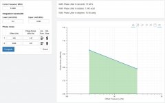
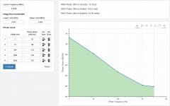
As you can see, in the first picture the jitter is calculated with an integration bandwidth 300Hz-3KHz (the standard used in telecommunication), while the second pictures shows the jitter calculated with a wider integration bandwidth, more suitable in digital audio, 1Hz to 3KHz.
The first picture tells us that the oscillator has a jitter of 37.84 fs, that's a great result! Almost like the MSB Tech Femto 33 (33 fs).
So, why you can get the Crystek for 25 Euro while you have to pay 19000 USD to get the MSB?
It's very strange such that difference if they are so similar!
The second picture explain clearly the reason: with a suitable integration bandwidth the jitter of the Crystek grows to 12.28 ps, that's almost one order of magnitude (fs to ps) worst than the MSB one.
I've not succeeded explaining this to the fundamentalist followers, maybe somebody could try one more time.
Since someone in another thread claims that the jitter measurement with a digital oscilloscope is the right and absolute way to understand the timing quality of digital audio devices (and obviously his fundamentalist followers confirm this without understand what they are talking about), I publish a pair of pictures to explain the reason why such that way is wrong.
I have used a phase noise to jitter converter to emulate the jitter measurement of the Crystek CCHD-957 at 22.5792 MHz.
The calculated jitter is exactly the same that one can measure with a real gear.
As you can see, in the first picture the jitter is calculated with an integration bandwidth 300Hz-3KHz (the standard used in telecommunication), while the second pictures shows the jitter calculated with a wider integration bandwidth, more suitable in digital audio, 1Hz to 3KHz.
The first picture tells us that the oscillator has a jitter of 37.84 fs, that's a great result! Almost like the MSB Tech Femto 33 (33 fs).
So, why you can get the Crystek for 25 Euro while you have to pay 19000 USD to get the MSB?
It's very strange such that difference if they are so similar!
The second picture explain clearly the reason: with a suitable integration bandwidth the jitter of the Crystek grows to 12.28 ps, that's almost one order of magnitude (fs to ps) worst than the MSB one.
I've not succeeded explaining this to the fundamentalist followers, maybe somebody could try one more time.
Attachments
You are right, I meant one order of magnitude of measurement unit (fs to ps) that's 3 orders of magnitude mathematically speaking (x 10^3).
I would like to see some real specs on the MSB oscillators. The claims are pretty extravagant and you show how to get better numbers. Most comm standards use a higher range for measuring jitter (e.g. Sonet 12 KHz to 20 MHz) and will give lower rms jitter numbers. This is a good intro to the many ways to look at jitter: An Introduction to Jitter in Communicatio - Maxim Integrated and this for a premium oscillator mfr: http://www.mtronpti.com/sites/default/files/files/oscillator-jitter-basics.pdf
My point being that you need to know what to measure for before measuring jitter. Early on this thread was about evaluating the importance of low frequency components of jitter. Its not simple since the published evidence of jitter sensitivity shows that HF parts are more important.
I would still argue that what is important is the jitter artifacts in the audio output. Those are easier to measure since all you need is a good soundcard and FFT plus some digital test tones.

- Status
- Not open for further replies.
- Home
- Source & Line
- Digital Line Level
- The Well Tempered Master Clock - Building a low phase noise/jitter crystal oscillator