You are on the right technical path Andrea - just build it and don't get to involved in what others think or do. The pudding will be jummy.
//
//
If you follow Ian's threads closely there are many reports suggesting the FIFOpi performance is influenced by the Rpi. Power supply to Pi counts. Supercaps to Pi makes a difference. People have changed regulators on the Pi PCB to improve sound. And replacing the stock Pi with the Allo USBridge makes a big improvement in sound. I have experienced many of these.
I know, but nobody wants to discuss it, we continue debating around the RPi rather than the measurements of the FifoPi.
I would not want to replace anything in a device so called "ultimate".
Yes. Just do it. Sounds good.
No need to attack others..
"" would not want to replace anything in a device so called "ultimate". ""
Like here. Again
No need to attack others..
"" would not want to replace anything in a device so called "ultimate". ""
Like here. Again
You are on the right technical path Andrea - just build it and don't get to involved in what others think or do. The pudding will be jummy.
//
Thanks for the trust, we hope to achieve the goal, but the road is long, it will take a long time.
The strange thing is that in post #2535 I have published a pair of phase noise plots and asked a few questions, but no one answered.
And You did not answer at all to the point of Ian about those two SCK curves which would be supposed equal, instead are showing 10 / 20dB difference between them.
So before demanding answers, You should decide which of your's curves are valid..
Post #2536 ;
Attachments

Last edited:
Yes. Just do it. Sounds good.
No need to attack others..
"" would not want to replace anything in a device so called "ultimate". ""
Like here. Again
Joseph,
I don't want to attack anyone, I have published some measurements for the audio cummunity (spending a lot of time) and these could be discussed to improve the device, instead to keep debating around the RPi.
Moreover if someone has been attacked that's me, since the measurements have been described as "unreliable" several times.
Because indeed there are curious quirks, see above..
It is not attacking, it is also to clean up the situation.
It is not attacking, it is also to clean up the situation.
The RPi SCK plots in posts #2536 differs only about the spurs (disabled/enabled), the phase noise at 10 Hz from the carrier is identical (-102 dBc).
Even the FifoPi SCK plots in posts #2535 and #2536 are identical.
If you want I can send you the .tim files so you can load them in the Timelab and manage them as you want.
But I see you continue arguing about the RPi, avoiding to talk about the FifoPi.
There would be some other question to clean up the situation, such as the analogical view of the LRCK after the FifoPi with time division set to 50 ns instead 2 ns or 20 us, but it seems you have forgot this.
Andrea!
You got the point! I had mixed up the curves!
Thank You.
About the other request, it seems You have forgotten that I'm not Ian, never used an Rpi & I2S and no FiFo here.. So I can not help you in that!
But what is the problem with the zoom in, one must do properly that, to be able to have a look at jitter..?
The strange thing is that in post #2535 I have published a pair of phase noise plots and asked a few questions, but no one answered.
Andrea,
Possibly the reason no one answered is that your not asking real "questions" - as you already know the answers (or you should do)...these are "leading" questions and your not educating anyone like this, but instead you come across as rather childish and rather insulting...
Your doing fine work experimenting and developing these clock circuits with the aid of your colleagues' TimePod (or maybe you have purchased your own unit by now) - but please try to remain humble and respective of others who are not lucky enough to have the access to such equipment to develop there own designs as far as you have been able too.
Its the learning that makes life interesting 🙂
Last edited:
Andrea,
I think John and George understand that in theory a FIFO should not be influenced by the source, but I suspect they are probably being very cautious not to be over confident that such effects are or can be fully eliminated. If spurs are not tracked down to the source, how can one be sure some stray coupling or some other unexpected mechanism is not caused by the source affecting the FIFO? Also, how could one be sure the spurs do not audibly affect dac performance regardless of their source? In my own experience, relying on standard measurements (e.g. AP tests) of dac performance is not enough to be completely sure there are no audible problems associated with spurs.
EDIT: Looks like John posted while I was still writing 🙂
I totally agree with you, at the end the tool I trust the most is my ear.
I spent several evenings in listening sessions since the early 90's when I cooperated to the design of an integrated amplifier which was then marketed under the Audiogram brand to fight with NAD, Naim, Rotel, Cambridge and so on, although it was a hobby for me even at the time.
But I think that each project must have a precise goal, the architectural choices are crucial and the measurements help a lot to understand the mistakes and the rooms for improvement.
With my measurements I thought I would help to improve a device which already has good performance against the price, but IMHO can be improved by thoroughly investigating the design choices.
Unfortunately my intention to help has been confused with the will to attack and discredit the designer.
I have already said many times that I bought a lot of stuff from Ian such as FIFO boards, I2S to PCM boards, isolators and so on.
So I experienced by myself that replacing the source the sound change, as pointed out from other members.
I believe this feature could be improved and I also believe that the measurements have already given some indications on the possible regions to be revised, and finally I have also suggested some update in these areas.
I thought I was helping and I'm sorry I was misunderstood.
@JohnW
I already own my Timepod and I thought I was using it to help who have not access to this tool.
I have not insulted anyone, I just tried to help.
I'm here to learn, and to help if I can.
Last edited:
Andrea,
Possibly the reason no one answered is that your not asking real "questions" - as you already know the answers (or you should do)...these are "leading" questions and your not educating anyone like this, but instead you come across as rather childish and rather insulting...
Your doing fine work experimenting and developing these clock circuits with the aid of your colleagues' TimePod (or maybe you have purchased your own unit by now) - but please try to remain humble and respective of others who are not lucky enough to have the access to such equipment to develop there own designs as far as you have been able too.
Its the learning that makes life interesting 🙂
Nonono, please don't be criticise. I could say anything to anyone else, but then what would happen?
Just let the discussion go on, we all know Andrea and Ian will find the way for their products. We shall all thanks to their contribution to the community.
Ken
Andrea,
I wanted to say something similar to John, about your questions, plus that I don't feel OK to descend into remote debugging something I do not have at hand.
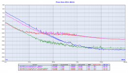
But would like to add: Your comparison 'chart', the FiFo SCK curves with two different clocks are indeed a nice help, and show that with a higher close-in phase noise oscillator the theory does work, the division by 2 do bring a - 6dB premium.
(So the FiFo is an adeguate solution to extract the best from the oscillators it is used with typically.)
With the better quality, Driscoll oscillator the inherent phase noise limit of the FiFo itself had been reached, and the result is not following the division rule any more.
So with these tests You mapped the FiFo's own phase noise contribution borders.
In the same time this limitation shows up as 'noise', noise floor modulation, not 'spurs' like it would be with deterministic contribution.
But signal feedtrough, what You are suspecting, even more, synchronous signal leakage is proper, typical deterministic jitter source.
So I think You search at the wrong part...
Noise floor could be more connected to power supply noise, device noise limitations..? Guessing.
Logic gates are 'defenseless' against PS noise, very low PSRR.
Ciao, George
I wanted to say something similar to John, about your questions, plus that I don't feel OK to descend into remote debugging something I do not have at hand.
But would like to add: Your comparison 'chart', the FiFo SCK curves with two different clocks are indeed a nice help, and show that with a higher close-in phase noise oscillator the theory does work, the division by 2 do bring a - 6dB premium.
(So the FiFo is an adeguate solution to extract the best from the oscillators it is used with typically.)
With the better quality, Driscoll oscillator the inherent phase noise limit of the FiFo itself had been reached, and the result is not following the division rule any more.
So with these tests You mapped the FiFo's own phase noise contribution borders.
In the same time this limitation shows up as 'noise', noise floor modulation, not 'spurs' like it would be with deterministic contribution.
But signal feedtrough, what You are suspecting, even more, synchronous signal leakage is proper, typical deterministic jitter source.
So I think You search at the wrong part...
Noise floor could be more connected to power supply noise, device noise limitations..? Guessing.
Logic gates are 'defenseless' against PS noise, very low PSRR.
Ciao, George
Last edited:
George
Your theory makes sense. If we have reached the limitations of FIFOPi with the Driscoll oscillator, then it seems consistent with sound quality varying with efforts to reduce noise in the FIFO itself. We see sound quality change with the PS to the FIFO, addition of supercaps and addition/change of caps on the pcb itself.
If all of this bears out to be the case, is there any practical benefit from upgrading from the Driscoll 45mHz to the 5mHz? Could be we have simply reached the limits of FIFOPi.
Though You don't know the real parameters of Your Driscoll oscillator.. That was pre-timepod era, am I right?
😉
😉
George
Your theory makes sense. If we have reached the limitations of FIFOPi with the Driscoll oscillator, then it seems consistent with sound quality varying with efforts to reduce noise in the FIFO itself. We see sound quality change with the PS to the FIFO, addition of supercaps and addition/change of caps on the pcb itself.
If all of this bears out to be the case, is there any practical benefit from upgrading from the Driscoll 45mHz to the 5mHz? Could be we have simply reached the limits of FIFOPi.
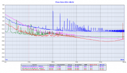
Maybe the limits of the FifoPi has been reached with the Crystek too.
Above 30-40 Hz from the carrier the phase noise overcomes the noise of both oscillators, at 1 KHz from the carrier there are 25 dB difference with the Crystek and 30 dB with the Driscoll.
So the question is: why the FifoPi sounds better with the old Driscoll oscillator against the Crystek?
The master of clock Pat Di Giacomo, as you probably know as Jocko Homo, pointed out the reason some time ago: the phase noise close to the carrier, 10 Hz and below, where our brain is more sensitive to the timing error.
As you can see from the plot, although the phase noise is similar above 30 Hz with both oscillators, there is a big difference in the close in noise, around 20 dB.
So I believe you can expect a further improvement with the new Driscoll at 5 MHz, because the close in phase noise will be around 25-30 dB better, although I don't think there will be an improvement above 30-40 Hz from the carrier.
Attachments
New Differential oscillator
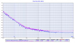
The Differential oscillator is ready, I attach the phase noise plot with the crystal at 5.6448 MHz compared with the Driscoll.
The blue line is the new Driscoll while the pink line is the new Differential.
They are very similar, the Driscoll has 5-6 dB better noise floor, the close in phase noise is almost identical.
The noise floor difference is probably due to the different location of the crystal in the circuit, in the Driscoll the crystal is in the emitter circuit while in the Differential it's in the feedback loop.
Anyway they are both real very low noise oscillators, in the region of BVA and ULN.
Attachments
The master of clock Pat Di Giacomo, as you probably know as Jocko Homo, pointed out the reason some time ago: the phase noise close to the carrier, 10 Hz and below, where our brain is more sensitive to the timing error.
This would make perfectly sense if one correlates the listening tests and experience of several users with the objective measurements.
So how does a phase noise curve would look round 10Hz between a cheap standard Clock and the Crystek ? That would support the thesis as the community also reported improvements here.
And on a separate note, if the 10 Hz is the key area, why are we still making curves far beyond that and integrate the result in the total metric number ?
Secondly, why all the fuzz about the fifopi having a high noise floor above 100 Hz ? it seems to do the job around 10 Hz right ? So everyone could and should be happy ?
- Status
- Not open for further replies.
- Home
- Source & Line
- Digital Line Level
- The Well Tempered Master Clock - Building a low phase noise/jitter crystal oscillator