Quick audio tests today :
On a pair of Klipsch Heresy I (with modified balanced crossover) :
No issue : the amps delivers the sound and performance as the protoype did, with a dead quiet S/N ratio.
End of the saga !
A+!
An externally hosted image should be here but it was not working when we last tested it.
On a pair of Klipsch Heresy I (with modified balanced crossover) :
An externally hosted image should be here but it was not working when we last tested it.
No issue : the amps delivers the sound and performance as the protoype did, with a dead quiet S/N ratio.
End of the saga !
A+!
Don't you worry about the asymmetric sine waves? It indicates 2nd harmonic distortion, which might sound nice tubey...Sine waves at 4 and 8 Watts Rms output :


Don't you worry about the asymmetric sine waves? It indicates 2nd harmonic distortion, which might sound nice tubey...
Well, here are the performances measured on the 2008 prototype shown at the start of this thread :
THD for 1KHz Sinus @ 8ohm resistive load, no NFB loop :
HI 10W = 5.32% (at the threshold of clipping)
HI 8W = 3.75% (at the nominal power)
HI 4W = 1.69%
HI 1W = 0.7%
LO 5W = 4.96% (at the threshold of clipping)
LO 4W = 3.50% (at the nominal power)
LO 1W = 0.85%
Bandwith @-3dB/8Wrms = 8Hz-25khz
On the final version, the results should be nearly identical, since the waveforms are the same as the one I obtained with the 2008 prototype. The distortion on the prototype was measured with the help of spectrum analyser, showing the usual 300B regular harmonic decay, with predominant H2.
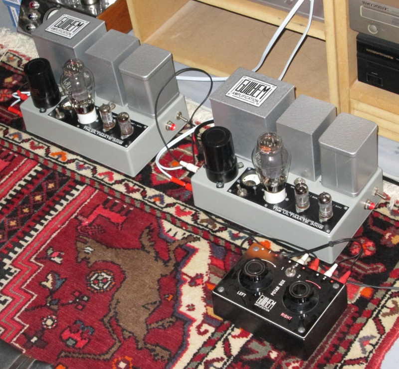
Nice, but I don't think you have enough speakers...
I agree... But then it is a matter of small room 😱
An externally hosted image should be here but it was not working when we last tested it.
That's the reason why I could never built a final version of those big prototypes 🙁 :
An externally hosted image should be here but it was not working when we last tested it.
A+!
U-300B Thread Resurrection
Thread resurrection :
I've been contacted by member @kmtang about my U-300B, and since my previous pic hosting provider has collapsed, I saw that no more informations were available on the subject... 😱
So I repost most of the details here... Click on the pics for zoom 😉
The original wooden prototype :
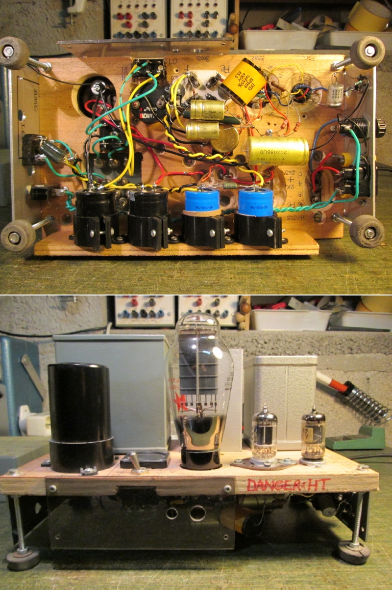
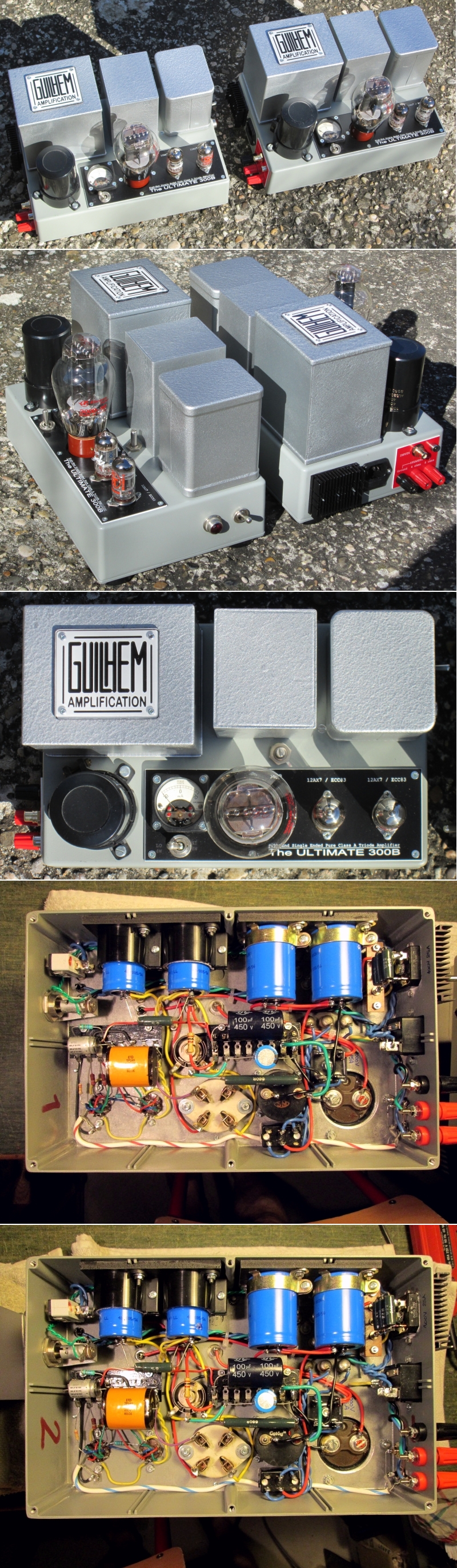
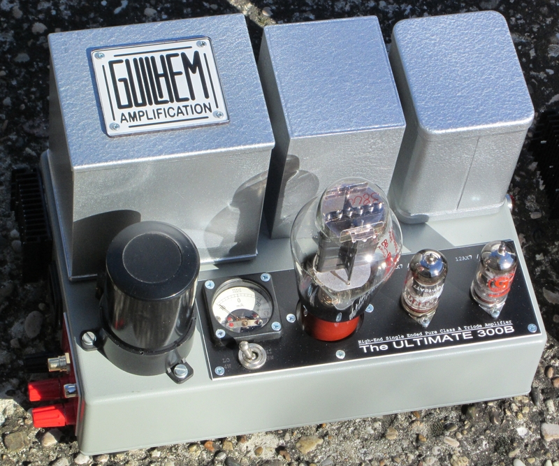
The final built :
The performances :
THD for 1KHz Sinus @ 8ohm resistive load, no NFB loop :
HI 10W = 5.32% (at the threshold of clipping)
HI 8W = 3.75% (at the nominal power)
HI 4W = 1.69%
HI 1W = 0.7%
LO 5W = 4.96% (at the threshold of clipping)
LO 4W = 3.50% (at the nominal power)
LO 1W = 0.85%
Bandwith @-3dB/8Wrms = 8Hz-25khz

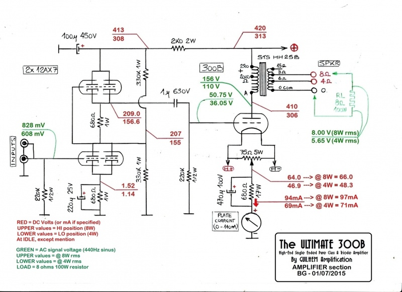
The schematics :
A+!
Thread resurrection :
I've been contacted by member @kmtang about my U-300B, and since my previous pic hosting provider has collapsed, I saw that no more informations were available on the subject... 😱
So I repost most of the details here... Click on the pics for zoom 😉
The original wooden prototype :
The final built :
The performances :
THD for 1KHz Sinus @ 8ohm resistive load, no NFB loop :
HI 10W = 5.32% (at the threshold of clipping)
HI 8W = 3.75% (at the nominal power)
HI 4W = 1.69%
HI 1W = 0.7%
LO 5W = 4.96% (at the threshold of clipping)
LO 4W = 3.50% (at the nominal power)
LO 1W = 0.85%
Bandwith @-3dB/8Wrms = 8Hz-25khz
The schematics :
A+!
Seriously, thats an ill fated circuit.
300B needs a beefy driver tube but nevertheless a paralled 12AX7. Never seen such a strange thing in my life. And I've seen hundreds of excellent 300B amps.
300B needs a beefy driver tube but nevertheless a paralled 12AX7. Never seen such a strange thing in my life. And I've seen hundreds of excellent 300B amps.
Seriously, thats an ill fated circuit.
300B needs a beefy driver tube but nevertheless a paralled 12AX7. Never seen such a strange thing in my life. And I've seen hundreds of excellent 300B amps.
We learn every day, don't we ? 😀

A+!
Seriously, thats an ill fated circuit.
300B needs a beefy driver tube but nevertheless a paralled 12AX7. Never seen such a strange thing in my life. And I've seen hundreds of excellent 300B amps.
Agree.
2.2 mA does not drive a 300B grid well; worst 300B circuit I have ever seen 🙁
The only thing to be learned from this is doing it different and better.
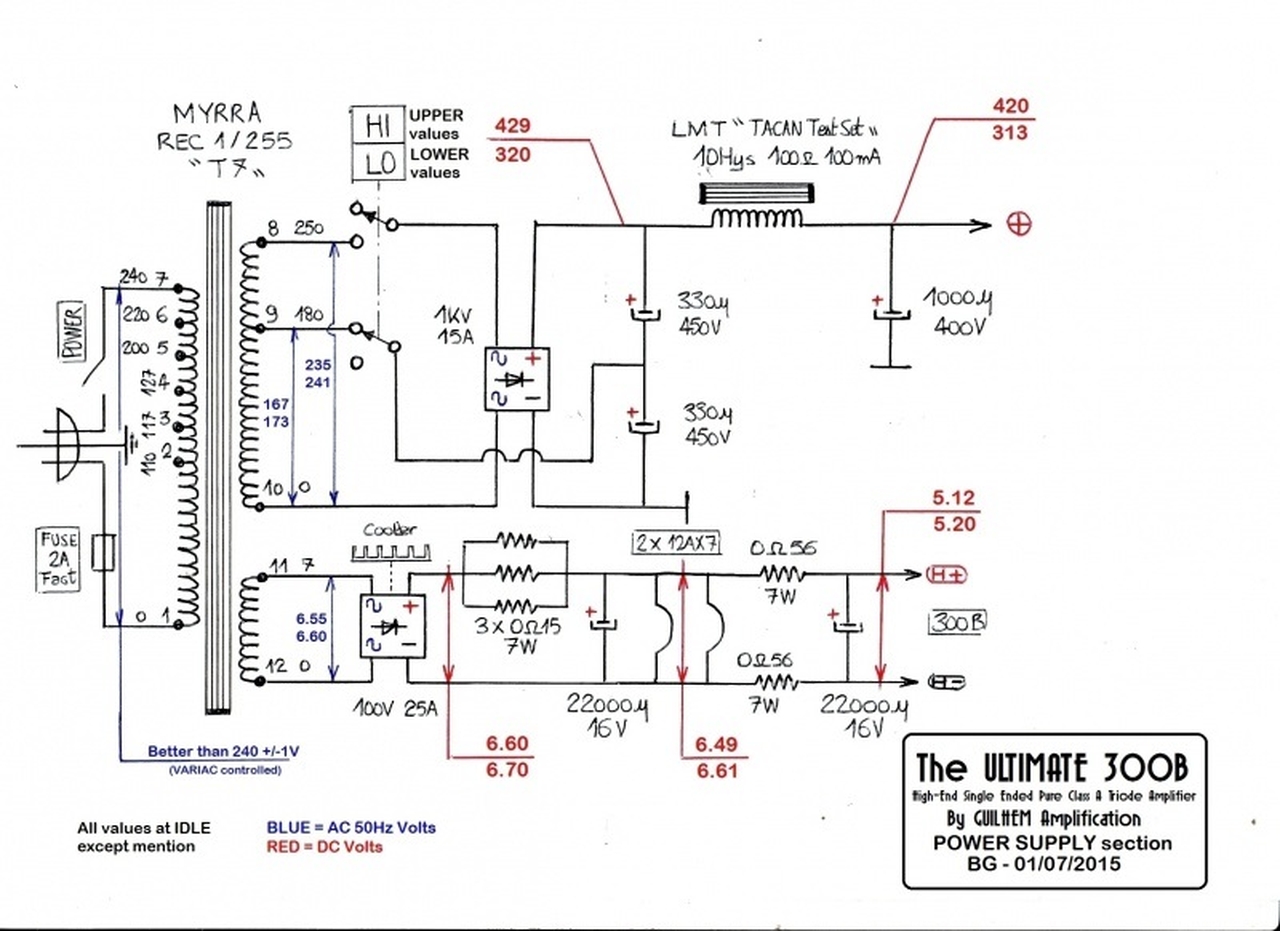
Also, the Hi-Lo switch in the HV power supply will not work as drawn...
Last edited:
tubelectron,
Great looking amplifier!
Great looking sine waves!
Just a very small 2nd harmonic distortion at the higher power level, should sound great.
Yes, you made the Bumble Bee fly, even though the engineers said it could not fly.
But please, at least balance the currents in the four 12AX7 triode sections.
Use 4 individual self bias resistors.
1. Use 4 each 1360 Ohm resistors, one for each cathode (individual self bias).
2. Use 2 each 100uF caps, one each across each of the bottom 1360 Ohm resistors.
1360 Ohms AND 100UF is -1 dB @ 2Hz, good enough. Your speakers do not do 2Hz.
3. Use 2 each coupling caps, 0.1uF, one from each of the top cathodes at the junction of the top of the top two 1360 Ohm self bias resistors.
That gives - 1dB @ 14Hz, good enough. Your speakers do not do 14Hz.
(A 1uF cap, and 220k grid resistor has a terribly long recovery time after any 300B grid current causes blocking).
4. Get rid of those two 330k resistors.
If the tubes will not bias up to near 1/2 of the voltage of the top plate, then purchase some good 12AX7 tubes.
Do not fix bad tubes by making the circuit worse.
Try all that, and report back, please.
I expect a good amp will be made even better.
Note:
You may experience trouble because the top 12AX7 cathodes are at about 200V, but the filaments are only at about 47 or 64 volts.
That may cause some leakage current from the filament to cathodes of the top 12AX7 tubes.
You are close, the maximum heater to cathode spec is 180V. Just be sure to check at what voltage those cathode are at.
Actually, the signal will drive the cathodes to a much higher voltage.
You may need to use a separate 6.3V filament transformer for the top triode sections, and elevate that with a resistive divider from B+, and a bypass cap.
Last edited:
Why would it won't work? The LOW position is a voltage doubler the high is a full wave rectifier with the higher tap....Agree.
2.2 mA does not drive a 300B grid well; worst 300B circuit I have ever seen 🙁
The only thing to be learned from this is doing it different and better.
Also, the Hi-Lo switch in the HV power supply will not work as drawn...
Then why it would not be capable to drive the 300B, do you know what miller capacitance is? and how much is expected in the circuit, cause not every one has a D3a tube in its pocket......
At least as far Im concerned a pair is more expensive than the whole amp 😡
Sorry but to much negativeness around, please if you have an greater idea post a graph or a sim or something, and don't come saying the measuring dont mean nothing cause that invalidates your coment and also the whole purpose of this forum.
Yes I know what miller capacitance is, and what is needed to drive a DHT like 300B.
Maybe reading this, especially Rod's explanation, makes clear why even a parallelled 12AX7 is not up to the task:
12ax7 driving a DHT out, why not?
12AX7 driving a 300B works and it "sounds", but direct heated power triodes require better drive to make them to perform.
Maybe reading this, especially Rod's explanation, makes clear why even a parallelled 12AX7 is not up to the task:
12ax7 driving a DHT out, why not?
12AX7 driving a 300B works and it "sounds", but direct heated power triodes require better drive to make them to perform.
Back-of-the-napkin calcs give me a SRPP output resistance in the neighborhood of 7.1k, in combination with the 220 grid leak total source impedance is just under 7.0k. This is actually a bit surprising for an AX7, but that's what SRPP gives as its benefit.
Miller capacitance around 36 pF, might want to add a few strays, so closer to 40-45 pF.
Frequency response is actually not too bad from 20-20k, though it is falling off. You could easily bode plot this or run a few voltage divider equations to show. The SRPP is not exactly known for low distortion, but it is SE after all. People don't tend to get too interested in distortion when they build a SE amp.
Slew rate would be a more significant analysis rather than straight up freq response, so documenting your distortion at say 20 kHz rather than 440 Hz as shown would help indicate how slew rate is affected. My guess would be not very good - for this reason I tend towards really strong drivers with output stages of several 10's of mA and only a few kohm. And without coupling capacitors.
But each person decides their own priorities.
.....The SRPP is not exactly known for low distortion, but it is SE after all... .
Oh boy, the old misunderstanding about SRPP.
It is not a SE circuit but fundamentally push-pull:
The Tube CAD Journal,SRPP Decoded
Oh boy, the old misunderstanding about SRPP.
It is not a SE circuit but fundamentally push-pull:
The Tube CAD Journal,SRPP Decoded
The output stage is SE, so the goal of this amplifier with overall lowest distortion is likely not a priority. My statement was made not about the specific input stage, but the amp as a whole.
Geez, I was actually in agreement with your statement that the stage does not drive the 300B properly. Thought I would help by at least making a few calcs, which Post 30 challenged you to add. The things you choose to take issue with🙄
The Quad of triodes in two 12AX7s can adequately drive the 300B miller capacitance.
There may, or may not, be enough peak to peak voltage swing to give 2X the 300B Bias, so it may not reach full power out.
1. Bandwith:
300B rp = 700 Ohms
Load = 2500 Ohms
Gain = u x (2500/(2500 + 700)
Gain = u x (2500/3200)
300B u = 3.85
Gain = 3.85 x (2500/3200) = 3.0
300B Cgp = 15pF
Miller capacitance = 3.0 x 15pF = 45 pF
Xc = 1/(2 x pi x f x C), let f = 20kHz, C = 45pF
Xc = 530k Ohms
Miller Xc at 20kHz = 530k Ohms.
A quad of parallel 12AX7 triodes in SRPP mode Can drive the Miller capacitance of a 300B reasonably well.
The 300B grid resistor is 220k. At 20kHz, that is in parallel with Miller Xc of 530k.
The 220k is approximately 2/3 of the total load on the SRPP.
The amplifier works for most of us.
2. Slew Rate:
At 20kHz, a slow slew rate can cause 2nd harmonic distortion.
Consider a piccolo playing a 4000Hz note:
The 5th harmonic is at 20kHz, and it will be distorted by the amplifier’s low slew rate.
That 20kHz (5th harmonic) of that Piccolo will be distorted by the amplifier.
That amp will create 2nd harmonic distortion at 40kHz.
Can you tell me that your speakers actually can reproduce 40kHz?
Can you tell me that you actually can hear 40kHz?
If you are one of the few in the world, then you can say yes to both of those.
Now you do have a problem, because you can not listen to that amplifier.
The rest of us just listen to that amplifier, and we enjoy the music.
3. If you are looking for the ultimate in fidelity, attend a concert.
When was the last time you did that?
Well, the Corona virus has skewed the answer to that question.
Last edited:
Cin = Cgk + Cga(1 + A)
Cin = 8.5pF + 15pF * (1+3)
Cin = 68.5pF
+ some parasitic capacitance of wiring and socket, so 70pF as an estimate not exaggerated.
---------------------------------------
Miller Effect (Slew rate current) | VT52.com
"yet at 70V swing the 300B requires 1.07mA
NOTE: To be sure the driver can handle these currents, multiply by 5 to see what bias current the tube should have. In case of the 300B, the driver should be biased at a minimum of 5mA in order to operate without any problems."
The output stage is SE, so the goal of this amplifier with overall lowest distortion is likely not a priority. My statement was made not about the specific input stage, but the amp as a whole.
Geez, I was actually in agreement with your statement that the stage does not drive the 300B properly. Thought I would help by at least making a few calcs, which Post 30 challenged you to add. The things you choose to take issue with🙄
Sorry zigzagflux ... I was a bit rude.
Actually I was annoyed to see a weak driver stage in a circuit presented as "The ultimate 300B".
We know that SE 300B amplifiers can only be as good as power supplies, input/driver stages and output transformers allow them to be.
In this case conditions are not met to create what might be called "ultimate", despite 6A3sUMMER's kind suggestions for some improvement.
With two noval sockets it is not difficult to create a better input/driver stage.
For example an Aikido style input/driver stage with 12AX7 and 5687.
Or single 12AX7 SRPP input, direct coupled to a 12B4 cathode follower.
Multiple options to bring this amp to a higher level without the need to build a completely new amp.
Last edited:
I often listen to my friend EF86-12AX7-PL36 push-pul on Altec Lansing Model 9. It's an amazing sound, unbeaviable, 5++++++.
On the same speakers, 12ax7-12ax7-300B (or so) is very very very skinny.
6A3sumer, I respect you very much, but you will hardly convince me.
If you want a good sound from the 300B SET, stay with the German post tube as driver. I tried 20 drivers for 300B SET
Just IMHO
On the same speakers, 12ax7-12ax7-300B (or so) is very very very skinny.
6A3sumer, I respect you very much, but you will hardly convince me.
If you want a good sound from the 300B SET, stay with the German post tube as driver. I tried 20 drivers for 300B SET
Just IMHO
Last edited:
Yes, stay with Sakuma San. Same driver tube as output tube.
An EL34 is a very good driver. That gives flash and blood to the sound. No skinny girls wanted here.
An EL34 is a very good driver. That gives flash and blood to the sound. No skinny girls wanted here.
At 20kHz, a slow slew rate can cause 2nd harmonic distortion.
Consider a piccolo playing a 4000Hz note:
The 5th harmonic is at 20kHz, and it will be distorted by the amplifier’s low slew rate.
That 20kHz (5th harmonic) of that Piccolo will be distorted by the amplifier.
That amp will create 2nd harmonic distortion at 40kHz.
Can you tell me that your speakers actually can reproduce 40kHz?
Can you tell me that you actually can hear 40kHz?
If you are one of the few in the world, then you can say yes to both of those.
Now you do have a problem, because you can not listen to that amplifier.
The rest of us just listen to that amplifier, and we enjoy the music.
I have wondered about this myself, and tend to take the position that we can perhaps tell the difference. I think the rub (or let's call it the unknown) is that the human ear does not perform identically to an FFT analyzer. I have no question that I cannot hear a 40kHz sine wave; but that's not the real question; can I tell the difference between a 'clean' piccolo and a distorted piccolo. Just because the distortion is 5th/10th (and therefore out of my hearing range for pure sines) does not imply the fundamental sounds the same to my ears. Might be an interesting experiment, but I highly doubt it just comes down to treating my ears as if they operate like a FFT.
I take a somewhat similar argument to the speaker. Maybe it cannot reproduce a 40 kHz sine wave, but give it a symmetrical square wave at 10 kHz and ask yourself if it sounds identical to a sine wave. Then again, some swear by the supertweeter; never had one myself.
Slew rate is a complex distortion that affects rise/fall times, tending to cause phase shift of the original fundamental as well. And rarely is this phase shift the same on rising vs falling edges. It's a whole lot more complex than just adding 2nd distortion. Since music is such a complex signal and looks nothing like straight sine waves, slew can mess with signals (in this amp) at frequencies much less than 20 kHz.
Rather than personally getting into a tizzy about whether or not I can hear it, I choose to make my drivers beefy with enough standing current to tackle loads 2-3 times what I ever expect, and the answer becomes moot. I have no problem pushing some grid current; ask this amp to do so and watch it fall apart. So it's really a matter of understanding the limitations of a design, and accepting them as they are (unless mods are in its future). Perhaps with too much debate this design has been attacked rather than admired for its qualities. But it isn't me calling my designs Ultimate....
- Home
- Amplifiers
- Tubes / Valves
- The ultimate 300B