hello designers!
was born a new theory that you can not ignore
since VAS the transition more delicate for signal
need natural Compensation for those who want a sound round
OF COURSE FOR COMLEMENTARY ARCHITECTURE
there is the problem of actual similarity of the couple
(even in the life of humanity)
a solution is to use pairs of low-power
because they are much closer
and a stadium load to mosfets
because reduce emphasys of driver
Another solution is to offer an identical load to mirror current
(also have voltage gain)
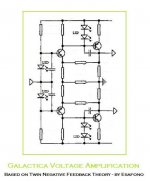
the new bright idea is to use a double NFB
in order to manage the different gain separately
before they mix in current stage
NOT in VAS as floating mode


was born a new theory that you can not ignore
since VAS the transition more delicate for signal
need natural Compensation for those who want a sound round
OF COURSE FOR COMLEMENTARY ARCHITECTURE
there is the problem of actual similarity of the couple
(even in the life of humanity)
a solution is to use pairs of low-power
because they are much closer
and a stadium load to mosfets
because reduce emphasys of driver
Another solution is to offer an identical load to mirror current
(also have voltage gain)
the new bright idea is to use a double NFB
in order to manage the different gain separately
before they mix in current stage
NOT in VAS as floating mode
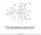
Attachments
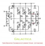
Something wrong seems to me in schematic, if GND means ground.
Grounded driving point (common point of 100R rersistors)of output devices (drivers loaded with 100ohms to ground??), drivers and ouput transistors outside of NFB..
Grounded driving point (common point of 100R rersistors)of output devices (drivers loaded with 100ohms to ground??), drivers and ouput transistors outside of NFB..
it's correct like this
Hello
GND on mosfets drivers is forced for TNFB (TwinNFB) reference
you can joint to transistor on output
it's not important
current stage is free from NFB because don't have gain in Voltage
Nelson I have seen F5
there are two NFB because it's balanced
this Sound's Revolution Amp have two NFB, one one each rail
for auto-adjusting different gain of PNP/NPN
in separate devices for better error-control
maybe (never tested)
Regards 🙂 😎
Been there, done something like that, not really thinking about doing it again sometime in my recent amps.. (maybe much later)..
Re: already exist in Current Stage
That is current limiting protection.
Tha aim to prevent the output stage from going ffzzzttt.
Cheers,
Glen
Stee said:need just in Voltage
a local feedback
the aim is to reduce the work of the input operational stage 😱
That is current limiting protection.
Tha aim to prevent the output stage from going ffzzzttt.
Cheers,
Glen
Thanks a lot Glen
but do you think it's intelligent
modify sensibility of this stage
to have double local feedback ( one for each rail ) ?
http://cgi.ebay.it/Bal-Class-A-Powe...39783QQcmdZViewItemQQ_trksidZp1742.m153.l1262
http://www.esafono.it/a700.pdf
Regards
but do you think it's intelligent
modify sensibility of this stage
to have double local feedback ( one for each rail ) ?
http://cgi.ebay.it/Bal-Class-A-Powe...39783QQcmdZViewItemQQ_trksidZp1742.m153.l1262
http://www.esafono.it/a700.pdf
Regards
Stee 🙂
just some friendly advice.
First,
you learn how to design some basic amplifiers, with transistors:
this will give you knowledge to know more
what we can do
what we can not do
what is good
what is not good
what is really problematic
what we never should do
what is usually the best to do
After this, you Stee,
can start making Mark Levinson clones, copy
And maybe one day even some great & working amplifiers based on your own interesting ideas.
But to get into the same league as Mark Levinson
is not what some new diy hobbyist will make very quickly.
Some would get close .. after many years.
Some would never make it .. no matter how long it takes.
What I have seen so far, is five or 10 ideas per day
.. only those posted 😀 😀 😀
and not many of them would work in reality.
It is good to have ideas
but what is the use, if they go nowhere?
🙂
you tell me
regars from
Lineup
Lineup Audio Lab - a few good amplifier ideas & designs based on knowledge & experience
lineup said:Stee
any news
.... or you put this Twin FB into garbage now 😀
No, he supposedly split everything on a complementary pair of amplifiers with own feedback in each one. 😉
just wait a week...
I have to do this test on famous Mark-China amplifier
with a double potentiometer on VAS
I have to do this test on famous Mark-China amplifier
with a double potentiometer on VAS
- Status
- Not open for further replies.
- Home
- Amplifiers
- Solid State
- The Twin Negative FeedBack Theory