It is a convoluted and counter-intuitive circuit: current flows in the backward direction wrt. to the voltage polarity, but the simple fact is that the circuit does work. Old foxes like John Broskie or jcx didn't miss it.Hi Elvee,
No, I really don't think so. Have you read the article carefully? There must be a reason why current would flow from one point to another. We know it's to equalize the charges, but I don't see that in the diagram.
-Chris
Discarding a good circuit on the grounds it it too difficult to grasp or to calculate is IMHO akin to intellectual lazyness.
This idea (without M1 M3 cascode) is debated on Russian forum for years
Please check what was done by others before starting promotion😉
Google Translate
Please check what was done by others before starting promotion😉
Google Translate
This idea (without M1 M3 cascode) is debated on Russian forum for years
Please check what was done by others before starting promotion😉
Google Translate
I think you missed the point:
The circuits shown are old classics, nothing esoteric: the tringlotron works by creating a negative resistance mirroring the non-linear properties of the amplifying elements.
The linearization process has nothing to do with any form of negative feedback: in fact it is the opposite, it works by applying a small and controlled amount of positive feedback.
PS:
A hint to that is input impedance: it is negative. None of the above circuits has this property.
Looks like its input impedance is quite low, it'd be hard to drive this buffer and keep the error in the previous stage remains small?
These circuits are old classics, they are variations on the Taylor / White theme.Apparently you have no time to open the link. Here are two circuits based on the same principle - Vbe error cancellation.
The topology probably has a name of its own, clever guys like kenpeter should know it.
The idea is to keep the current in the upper device as constant as possible.
No Vbe error cancellation occurs, merely a reduction.
As with any NFB based system, the factor of reduction is governed by the gain available, in this case from the servoing transistor (the lower one).
The tringlotron is one of the rare topology where true error cancellation occurs: the error voltage from the compensating transistor is actually substracted from the output; it is an open-loop process, which means there is no theoretical limit to the depth of the nulling (there are higher order effects limiting the accuracy, but this is another story).
Both topology bear a superficial similarity, but as soon as you analyze the inner workings, you realize that the mode of operation is not only different, but downright opposite.
This can be seen below: the green trace is the base current of the transistor in the modified Taylor circuit: as expected, it is nearly constant, and it is in phase with the input voltage (magenta).
The red trace is the equivalent in the tringlotron: the current has the full swing required to drive the load, but the phase is opposite to the input voltage.
This means the input resistance is negative, and that's the key to the "magics" of the circuit.
The result is a THD substantially lower than the conventional circuit on the left.
The aspects of the White, Taylor followers have been discussed by J Broskie:
Low Dissipation SE Class-A?
He has also examined the tringlotron:
Tringlotron
[edited at members request]
Attachments
Looks like its input impedance is quite low, it'd be hard to drive this buffer and keep the error in the previous stage remains small?
It is worse than low: it is negative.
For the MOS version, this is less of an issue, but it could easily oscillate due to the parasitic capacitance.
The best solution is either to build the complete tringlinator, or at least to include buffer Q5 and Q6.
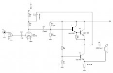
To show how outlandish and completely unlike anything else the tringlotron is, here is a little exercise:
The circuit, although originally intended as a precision unity gain buffer, can also work as an amplifier.
You just have to add a resistor in series with the input!.
A parallel 100pF is also included, to ensure stability.
A resistor in series with the emitter of Q1 has a similar effect.
No other buffer topology has such esoteric properties.
Attachments
These circuits are old classics, they are variations on the Taylor / White theme.
The idea is to keep the current in the upper device as constant as possible.
No Vbe error cancellation occurs, merely a reduction.
Thank you, now we are talking the same language.
Conventional follower: input = output + Vbe
Taylor/White - current in the upper device is constant, input = output - Vbe of lower device, current change in lower device has different sign
Your follower - M1 and M2 share the same current, and if devices are identical - the same Vbe. Vbe of M1 (which is equal to Vbe of lower device) is added to the input signal and applied to the gate of M3. Thus Vbe of lower device is subtracted from the output signal, the accuracy of subtraction is equal to accuracy of matching Vbe of M1 and M2.
Last edited:
Thank you, now we are talking the same language.
Conventional follower: input = output + Vbe
Taylor/White - current in the upper device is constant, input = output - Vbe of lower device, current change in lower device has different sign
Your follower - M1 and M2 share the same current, and if devices are identical - the same Vbe. Vbe of M1 (which is equal to Vbe of lower device) is added to the input signal and applied to the gate of M3. Thus Vbe of lower device is subtracted from the output signal, the accuracy of subtraction is equal to accuracy of matching Vbe of M1 and M2.
You have made a very neat summary, I couldn't have done it better.
And the accuracy of the matching between M1 and M2 is indeed critical (which is why the circuit does so well in simulation).
At this level of power, it is convenient to use a monolithic pair of MOS, which solves all problems of matching and thermal tracking:
http://www.irf.com/product-info/datasheets/data/irf7301.pdf
- Status
- Not open for further replies.
- Home
- Amplifiers
- Headphone Systems
- The Tringlinator: a MOS-based Tringlotron amplifier