A couple measurement thoughts before you build your next set of cabinets.
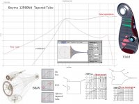
1) M-T physical time alignment. Typically a square wave is sent to M and T and delay difference is measured. Options for cabinet tweeks to get alignment can be considered. Special Xovers that shift driver phase to reduce time separation can be considered. The original TPL150H (80x30) horn has about 86mm of physical offset. The 12P80Nd could be mounted to match this with a minor front baffle set-back rim bevel. A measurement is better than any datasheet drawings guess.
2) Matching the polar response of the 12P80Nd to the TPL150(in some kind of horn) at the Xover frequency. Several diyAudio members who use the TPL150H agree that a 1600Hz Xover is very good choice. If you measure the polar response of the 12P80Nd around 1600Hz you will understand what horn horizontal beamwidth will seamlessly match. Today's best guess is that a 60x30 horn would be a better polar match at 1600Hz than the standard 80x30 production horn, but a good set of measurements are not on the web to confirm this. I posted Beyma's polar measurements of the TPL150H.
A couple other thoughts. I posted an aperiodic cabinet design for the 12P80Nd with F3 ~80Hz, and I also simulated this same cabinet with the vent sealed at estimated a F3 ~210Hz. You may consider developing a single sealed / aperiodic options cabinet. I favor putting fiberglass board like Owens 703 on all 3 internal sides to absorb the rear wave of a wide BW midbass like the 12P80Nd, your ears are better than a simulation.
Thanks for your input.
I have been reading the thread on quasi optimal crossovers and it looks doable. just have to find the center of the 12p80.
I am working on an elliptical 60 x 40 waveguide at present the current one is 40mm deep. I saw a polar plot for the 12p80 on here recently looks like the 60 degree is a good choice. Mostly doing this one to practice my wood carving skills and see how I like the look. I need to model it in hornresp to determine how deep it really need to be.
I saw your aperiodic cabinet post and was intrigued so I packed the waveguide with polyfil leaving a channel up to speaker, lost ~3db 80-200 Hz and lost a bit of definiton over that band as well. The 100 Hz TQW works quite well, almost exactly as hornresp predicts.
I have had good success layering fiberglass and felt, alternating layers, does much better than single material. Something about density changes and boundary's, from some class long ago.
Thanks again
Cheers
Cort
Tapered Tube Terminus.
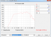
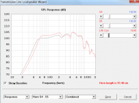
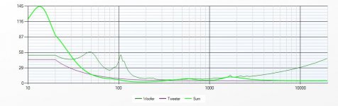
With Fs=45Hz and Qts=0.15 the Beyma 12P80Nd will always require a woofer.
I suspect that for sound quality a ~1cuft sealed box would be the normal first choice, which only reaches F3 of ~200Hz, which unfortunately pushes male voices into the woofer. One positive outcome is that a reasonable baffle size can be adjusted for a 200Hz 4-PI radiation compensation point, which can now be handled by just the woofer. A second positive outcome is total freedom from any Doppler type(hi+lo freq) IMD.
Putting an absorption stuffed open-end tapered tube behind the 1 cuft 12P80Nd box creates an aperiodic alignment which both extends the bass to F3 ~80Hz with modest bass shelf droop and modest phase shift increase, and the tapered tube also removes most box resonances without excessive cross bracing or excessive stuffing. (attached fig).
Both B&W and Vivid show good measurements on their website from putting an exponentially tapered tube behind a midbass. Vivid also uses side-side paired counterforce woofers. The white papers on the Vivid(ex-B&W engineers) are a great read.
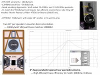
If the speakers are not planned to be placed right against a wall, two counter-force side firing 18" woofers like the Peavey Lo-Rider 479910 can provide >100db/watt sensitivity. More portable than a man-cave woofer horn. The two woofers could be in one box, and the MT in a second box with beveled edges for some diffraction control. The MT box should be ~2cuft total.
With Fs=45Hz and Qts=0.15 the Beyma 12P80Nd will always require a woofer.
I suspect that for sound quality a ~1cuft sealed box would be the normal first choice, which only reaches F3 of ~200Hz, which unfortunately pushes male voices into the woofer. One positive outcome is that a reasonable baffle size can be adjusted for a 200Hz 4-PI radiation compensation point, which can now be handled by just the woofer. A second positive outcome is total freedom from any Doppler type(hi+lo freq) IMD.
Putting an absorption stuffed open-end tapered tube behind the 1 cuft 12P80Nd box creates an aperiodic alignment which both extends the bass to F3 ~80Hz with modest bass shelf droop and modest phase shift increase, and the tapered tube also removes most box resonances without excessive cross bracing or excessive stuffing. (attached fig).
Both B&W and Vivid show good measurements on their website from putting an exponentially tapered tube behind a midbass. Vivid also uses side-side paired counterforce woofers. The white papers on the Vivid(ex-B&W engineers) are a great read.
If the speakers are not planned to be placed right against a wall, two counter-force side firing 18" woofers like the Peavey Lo-Rider 479910 can provide >100db/watt sensitivity. More portable than a man-cave woofer horn. The two woofers could be in one box, and the MT in a second box with beveled edges for some diffraction control. The MT box should be ~2cuft total.
Attachments
The tapered tube terminus is really cool, wish I had the room.
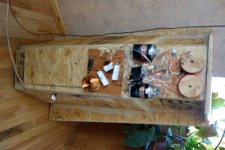
I was most concerned with the back wall reflections in my current cabinet it is pretty tight around the driver with just a couple inches clearance all around from the fiber glass. but I have done multiple sweeps above 110 db and did not see any resonances below 2 kHz. Certainly have not heard any.
The TQW models quite accurately in hornresp, I have been quite suprised.
Attachement 1 is ported to 40 hz it sounded good but did not compare to my bass horn and seemed to loose definitition across the entire bandwidth. that is with a 5 and a 10 cm portube. Currently the best for me is just the 2 3.5" holes.
But am planning to try a single 6" on the current baffle. Attachement 2.
Currently, the project has exceeded expections, especially the transitions between bass horn and 12p80 and the tpl 150 are seamless. I thought that was going to be more challenging.
I did succeed in designing a baffle to be up against a wall and eliminate the need for BSC.
I will admit that I was surfing 15 and 18 inch drivers today. as it seems to me that it would sound best if each driver was only required to cover 2 octaves. so the bass horn covers 20-80, then a 15 for 80-360 and the 12p80 360 to 1600.
Suggestions on a 15?
Cheers
Cort
Attachments
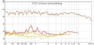
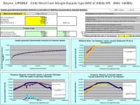
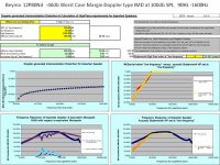
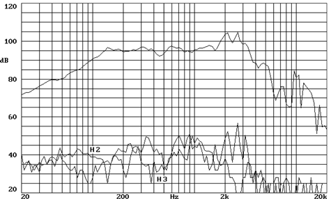
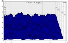
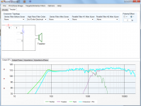
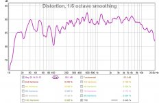
My statements above statements about not measuring any back wall reflections from the cabinets was really bothering me, so I looked closer at sundays measurements and they appear in the distortion plots at ~800 and 1000 Hz, 30 db down but still 10 db above the other harmonics
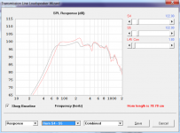
I am also curious about the group delay measurement. It is "flat" across the crossover point then drops above 3k. How do I interpret this? Is this time aligned?
I am also curious about the group delay measurement. It is "flat" across the crossover point then drops above 3k. How do I interpret this? Is this time aligned?
Attachments
I have found that when measuring with rew, you can take two measurements in a completely similar setup and you will have variation in the distortion numbers. I would make sure they are consistent before going to far with the analysis.
Thanks, my listening room is triangular with vaulted ceilings etc. so it seems like I am often chasing my tail with the measurements.
I agree that you will get better sound with a woofer(s) on the main cabinet, and the floor subs used to reduce bass room modes.
Attached simulation of 6” deep Parabolic Taper Aperiodic Load.
TPL150H sensitivity = 102db/watt.
12P80Nd sensitivity = 99.6db/watt. Good sounding alignments include 1cuft sealed F3=200Hz, and 1.2 cuft F3=85-90Hz aperiodic load.
To match the 99.6db/watt will require two efficient counter-force side firing 18" woofers like the $200 Peavey Lo-Rider 479910 or $350 Beyma 18XL60 rev1.
A single 18” woofer would reduce speaker sensitivity to ~94db/watt without bi-amp.
Attachments
I think you missed the "sub" I already have;
The Crawler, A Floor joist horn build
Check it out.
I did some horesp modeling last night of the aperiodic and the ml-tqw is better behaved and higher sensitivity for a 1.25 cu ft cabinet, which btw is what I am experimenting with.
Cheers
The Crawler, A Floor joist horn build
Check it out.
I did some horesp modeling last night of the aperiodic and the ml-tqw is better behaved and higher sensitivity for a 1.25 cu ft cabinet, which btw is what I am experimenting with.
Cheers
Do you believe in the Easter Bunny? The Great Pumpkin? Doppler Distortion?
Doppler type high+low_freq Intermodulation Distortion can become audible in wide BW speakers.
Simple conservative simulations of Beyma 12P80Nd IMD at 100db SPL estimate -40db margin at 90Hz Xover down to -16db margin at 50Hz Xover. -40db is often considered the audible threshold.
(Tapered tube stuffed lines should exit the rear of the box, but can then gently curve for flexible exit options, like a lower rear exit. Properly stuffed, very little sound should exit the tube)
Attachments
12P80Nd sensitivity = 99.6db/watt. Good sounding alignments include 1cuft
12p80nd simply is ~95db/w. take a look at frequency plot 😉 and forget about that hump at 2khz
I have heard the IMD with my box port tuned to 40 hz.
The aperiodic alignment looks like really good idea, but I have been unable to produce a decent model. linesource do you have a reference that may help me to understand how to model it correctly? In Hornresp?
This weekend I want to chase those couple of distortion peaks I measured as well as attempt to get decent impulse response measurements, for time alignment. Suggestions?
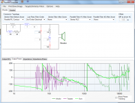
I got impedance's measured, everything loaded into winpcd, added 5uF to the low pass and took some measurements. All without room correction.
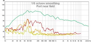
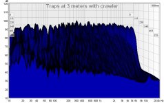
First I cranked the amp up to near 120 db and measured the near field of one of the ports. I wanted to make sure that there were no resonances coming from the ML-TQW
Second is full sweep response including sub.
Waterfall, waterfall at crossover and impulse all look good.
All measurements are 3 meters on axis from the one on the right.
Also did sweeps at 10, 20,30 and 40 degrees off axis and saw no evidence of beaming of the 12p80nd.
I still have an elliptical waveguide coming from Pellegrene Acoustics. They will have to wait until I build the new cabinets. Have to go for fire wood anyway hoping to find a stump I can take to the sawmill so they wil be bookmatched.
Cheers
Cort
Attachments
The aperiodic alignment looks like really good idea, but I have been unable to produce a decent model. linesource do you have a reference that may help me to understand how to model it correctly?
I've been using the free Transmission Line Modeling Software that Pete at Leonard Audio developed in the Software Tools Forum because it is easy to use, proven to be accurate, and simulates acoustic stuffing. At the rear of the box, a starting area equal to the speaker diameter is typically used. An exponential taper is used by B&W and Vivid. It is simple to graphically adjust volume and area with this tool.
http://www.diyaudio.com/forums/software-tools/220421-transmission-line-modelling-software.html
leonardaudio.co.uk
Transmission Line Modelling Software
===========
Augspurger AES papers: Part One: Modeling and Testing" and "Loudspeakers on Damped Pipes – Part Two: Behavior"
Some free downloads are available.
Augspurger provides optimized alignments (including required stuffing) based on Thiele-Small parameters for three TL geometries: tapered pipe, pipe with coupling chamber, and offset speaker. The woofer's VAS determines the required pipe volume while its free-air resonance frequency and pipe length determine the bass extension and overall Q of the system. In general, the bass half-power frequency (f3) for these designs can't be any lower than 80% of the nominal quarter-wave pipe resonance frequency (fp).
So I am a little confused linesource, are you promoting an aperiodic structure which is a bass reflex or a tapered terminus which is a tapered quarter wave structure? thanks for the link to the transmissionline software. I use hornresp, same math, same results benchmarkeds by other on this forum. I have modeled the offset tapered quaterwave ported from from either end and found that porting at the mouth gives 2-3 db higher spl. I would love to see if there is any measurable difference. As I am pretty happy with the measurements I have but would always like to do better.
It is cool that you mention the Auspurger AES papers. I was inspired down this path while I was building the mini statements and came across this thread;
http://www.htguide.com/forum/showthread.php?35563-Issue-Versions-of-Augspurger-Tables
Which inspired me to study TL theory then into horns resulting me designing and building the crawler which is an 8 meter long bass horns with an F3 of 16 hz.
Most telling though is Augspurger's current studio monitor
GA-215VS-A3 | Augspurger Monitors
which is a front ported cabinet,
Which is why my TQW design is on the edge of port loading and I have been experimenting with port loading of the cabinet.
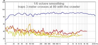
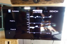
I have become familiar with psd lite and decided to go ahead and use the full capability of the software and add BSC, impedance correction, phase matching and ports to the Traps. Managed to take a quick sweep to make sure I didn't make any errors and it looks pretty good a couple db loss on the low end probably from the addition of the port tubes. Some day I will learn not to change 3 things at once, however the crossover is wired such that it will be easy to make changes and measure when I have a little more time. The audessy results are probably the smoothest I have seen for any speaker in my house.
Is this filter alignment acceptable? Am I missing something, making the wrong measurement etc...?
In pcd lite for offset is says MP to driver AC. Is that telling me that in order to be time aligned the tweeter needs to be 1.85 inches behind the acoustic center of the woofer in this case??
Cheers
Cort
Attachments

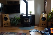
Hey there Cort.
Nice looking speakers.
One thing I have noticed is the vertical scale is a bit high.
Normal division is 5 db per line. You can zoom in with the +/- on the left side of the measurement window in REW:

Nice looking speakers.
One thing I have noticed is the vertical scale is a bit high.
Normal division is 5 db per line. You can zoom in with the +/- on the left side of the measurement window in REW:
Mark are you making AMT's now?
Yes.
That and many more.
XBL tweeter.
An Anarchy ish but longer excursion XBL 6.5
A XBL 5.25
Wideband 2.125
AN XBL 8 inch that has a real 16mm X-max
And the big boy.
XBL 15 34mm X-max ( Real not advertising poop ) 100mm coil subwoofer.
More in the wings.
So just a little bit busy.
Some of these will be going up on a group buy soon.
So enough of that stuff.
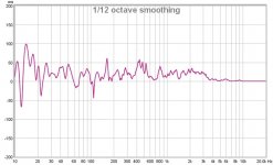
Your graph looks a little more realistic now. One sixth octave is pretty revealing, as it covers a span of only two notes per smoothing calculation. So much less smoothing than one third. Where most of the real music is your actually pretty darn good. 300 to 4 khertz looks pretty nice. The peaks may be room effects. You can find that out by close micing and seeing if they are still there. Close is 6mm (1/4") or less. Best is as close as is possible without hitting the diaphragm. This type of measurement will give you the least room related effects.
The floor bounce/ceiling bounce is very noticeable. You can calculate time of flight and distances from microphone to reflective surfaces and you will find that the really big dips are from those effects.
But as Linesource said with the subwoofer you have there can and will be modulation effects at times.
The air pulsing around you is an oh so cool effect right!
I think overall you have a pretty good crossover design.
- Status
- Not open for further replies.
- Home
- Loudspeakers
- Multi-Way
- The Traps, a ML-TQW experiment with Beyma TPL-150 and 12P80nd