Excellent description, I can almost 'see' it, and that's the way my screwy brain learns...🙂 Thanks much.
Actually, on the wire, she told me they just received their latest supply of that wire 10/16, so it may be the sheer bulk they buy allows them to sell it at less than half the cost of the closest competitor's price (??)...dunno...
Sounds like they'll keep supplying it though, so good news for other potential builders I guess...
I did happen to notice that wire is rated @150vrms, as opposed to the other I was quoted @600v (assuming peak).
See Attachment#1
Given the very low amperage ESLs run, I'm thinking no problems, but maybe someone more knowledgeable could chime in...😉
I just hope the insulating factor of the jacket is sufficient to resist breakdown (operating at my high(er) SPL expectation etc.)
Cheers
-Steve
Attachments

Last edited:
My stats use the same wire and I drive them pretty hard sometimes-- never observed any arcing. Yours will have about twice the area of mine so you would only have to drive them half as hard to get the same volume. I don't think you will have any problems.
Damn warehouse 'maroons' at Interstate sent me stranded wire (19/32)
I swear, the younger generation just doesn't listen, or plain just doesn't give a damn..🙄
Rant over..
Have two ESL related questions for anybody willing to answer:
1) If I make my panels 18" wide instead if 15" ... opinions on the issues I'm going to have to deal with? I'm thinking damping to reduce resonances etc.
Anything else? Construction issues? Other?
2) I was considering a dipole tower of 7" drivers, and I still may do that..
But what would be the drawbacks if I decided to go with two dual opposed 10's per side?
Lack of mid-bass 'punch'? Well anyway, open to anyone's' opinion...🙂
Cheers
-Steve
Hi,
2) true seamless transition requires the same distribution character appr. +-1oct around the x-over-frequency.
"two dual opposed 10's per side" what do You mean by that?
How´d that arrangement look like? In what casing?
If You´re talking about two Ripoles stacked above each other, the answer would be .... very probabely not enough dynamic range to keep up with the panel.
jauu
Calvin
Thanks Calvin,
Kind of figured that, but your explanation of distribution pattern is appreciated.
The "dual opposed" should just have been called dipole bass ? ....what I was thinking about is in the attachment:
Anyway, I was really just thinking/typing out loud again, and having a bit too much 'fun' last night..


Kind of figured that, but your explanation of distribution pattern is appreciated.
The "dual opposed" should just have been called dipole bass ? ....what I was thinking about is in the attachment:
Anyway, I was really just thinking/typing out loud again, and having a bit too much 'fun' last night..
Attachments
Last edited:
Hi,
no, that's no dipole bass
It's MLs way to create create good bass by optics and marketing ... failing in reality though 😎
jauu
Calvin
no, that's no dipole bass
It's MLs way to create create good bass by optics and marketing ... failing in reality though 😎
jauu
Calvin
Ah, I see.
I also had dipole and bipole mixed up, long night (and now day)
My head still hurts..lol...
Anyway, getting back to 18" width vs 15", looks like I could gain some dB, and bass cancellation would be at a lower frequency if I opted for the wider panel.
I think I'm going to be taking this route after debating with myself about it lately.
I went ahead and picked up another all-thread rod to make the stretching jig include a total of four tensioning rods.
I was going to go with three, but decided on four after thinking how much force it will take to cold stretch ~180-200 20 gauge wires.
Unless someone with more experience thinks this is a bad idea, and warns against some unforeseen (by me) future problems, that is...😉
Off to the shop with me...

@ wreckingball,
Received a message saying you had some questions concerning the ESL segmentation spreadsheet. I only read back a few pages, but couldn't find any. Were those the messages that were deleted? Appologies for not keeping up with things on diyaudio, didn't mean to leave you hangin...just life getting in the way. 😱
Received a message saying you had some questions concerning the ESL segmentation spreadsheet. I only read back a few pages, but couldn't find any. Were those the messages that were deleted? Appologies for not keeping up with things on diyaudio, didn't mean to leave you hangin...just life getting in the way. 😱
The two posts were deleted due to flaws, in general.
At first, the way I had this 18" panel planned was 24 segments @.75" each, with ~8 wires per segment, I soon realised a few things:
Those 24 segments are physical segments, and that the electrical segmentation is only 12.
Also, I had not calculated the vertical spacer widths (proposed @ .375") and with two, that's minus .75"
Then I remembered the center segment is a single .75" segment.
So with that, I'm thinking 12 electrical, and 23 physical, with two vertical lattice spacers taking up the remainder.
A single .75" center segment, and 11 electrical, (22 physical) segments to either side.
On track so far?
Secondly ..well I'll just post some screenshots and ask questions about them..
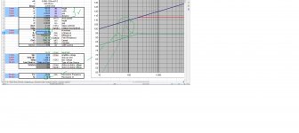
Attachment #1: This shows number of segments as 12, those are electrical segments, right? (otherwise, Feed R value is different with say, 23 sections for example)
*Mild suggestion to word it "# electrical sections" instead of just "# sections" on the worksheet. (for dummies like me..haha)
*I set the Q of the Fs at 10 which gives a big spike, notch filter candidate, right?
I have a question about the Feed R in next section.
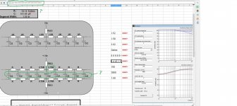
Attachment #2: There are a few things circled, I've some questions:
* I circled all the capacitance, this comes from the panel sections themselves, right?
*Up in the title/address bar, is this a list of all the resistor values one needs to construct the Rbank for their panel?
*The feed resistor is listed in the top grey portion, where in the 'chain' does this go? ..or point me to a thread?
*What relation does feed resistor have with the 4- 0.75R circled in the lower grey area?
*I see neither the feed resistor value, nor the 0.75R value reflected in the list of resistors in the title/address bar. (?)
Regarding that last point: I know you have put a lot of work into the program, plus all the help you give everybody, I just wish I knew how this all ties together.

I hope you can decipher all this, many thanks and much appreciated. 😉 🙂
At first, the way I had this 18" panel planned was 24 segments @.75" each, with ~8 wires per segment, I soon realised a few things:
Those 24 segments are physical segments, and that the electrical segmentation is only 12.
Also, I had not calculated the vertical spacer widths (proposed @ .375") and with two, that's minus .75"
Then I remembered the center segment is a single .75" segment.
So with that, I'm thinking 12 electrical, and 23 physical, with two vertical lattice spacers taking up the remainder.
A single .75" center segment, and 11 electrical, (22 physical) segments to either side.
On track so far?
Secondly ..well I'll just post some screenshots and ask questions about them..
Attachment #1: This shows number of segments as 12, those are electrical segments, right? (otherwise, Feed R value is different with say, 23 sections for example)
*Mild suggestion to word it "# electrical sections" instead of just "# sections" on the worksheet. (for dummies like me..haha)
*I set the Q of the Fs at 10 which gives a big spike, notch filter candidate, right?
I have a question about the Feed R in next section.
Attachment #2: There are a few things circled, I've some questions:
* I circled all the capacitance, this comes from the panel sections themselves, right?
*Up in the title/address bar, is this a list of all the resistor values one needs to construct the Rbank for their panel?
*The feed resistor is listed in the top grey portion, where in the 'chain' does this go? ..or point me to a thread?
*What relation does feed resistor have with the 4- 0.75R circled in the lower grey area?
*I see neither the feed resistor value, nor the 0.75R value reflected in the list of resistors in the title/address bar. (?)
Regarding that last point: I know you have put a lot of work into the program, plus all the help you give everybody, I just wish I knew how this all ties together.
I hope you can decipher all this, many thanks and much appreciated. 😉 🙂
Attachments
Last edited:
You are on track with your segmentation scheme. 
I have read and understand your questions and will provide some clarification tomorrow when I have a bit more time.
BTW, feel free to make suggestions on how to improve the spreadsheet tool.
It's certainly a bit rough around the edges still as it was never intended for public use.
I have read and understand your questions and will provide some clarification tomorrow when I have a bit more time.
BTW, feel free to make suggestions on how to improve the spreadsheet tool.
It's certainly a bit rough around the edges still as it was never intended for public use.
When I used the spreadsheet for my panels, I adjusted the inputs for width and height to encompass only the area of the panel that's actually covered by the wires-- which excludes the widths of the two 3/8 width center support spacers and the gaps between the spacers and wires. I believe this is correct.
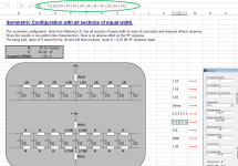
Your spreadsheet entries are correct for modeling Symmetric Configuration 2. Each electrical segment is 1.5” wide except the center one which is only 0.75”. The sum of the width of the physical segments and two vertical spacers does add up to 18”. Remember you will have some un-driven diaphragm area adjacent to the vertical spacers…usually something like 1/8” – 1/4” so don’t forget to take that into account when figuring total width of panel when building. But, as Charlie mentioned, you don’t include this in the width when modeling; continue to use the width covered by wires (both for width and height).So with that, I'm thinking 12 electrical, and 23 physical, with two vertical lattice spacers taking up the remainder.A single .75" center segment, and 11 electrical, (22 physical) segments to either side. On track so far?
Yes those are electrical segments, a carry-over from before the spreadsheet included physical layouts.This shows number of segments as 12, those are electrical segments, right?
*I set the Q of the Fs at 10 which gives a big spike, notch filter candidate, right?
I will clarify that label in the next revision of the spreadsheet.
If you don’t use any acoustic damping, your diaphragm resonance will indeed need to be handled electrically with a notch filter or very sharp HP filter. Some discussion on this in CharlieM’s first segmented build thread here: http://www.diyaudio.com/forums/plan...segmented-wire-stator-esl-19.html#post4241678
Correct, the capacitors you circled are the separate physical segments. The front and rear wire groups form the two plates of the capacitor.* I circled all the capacitance, this comes from the panel sections themselves, right?
The resistor value list that you have circled are values to copy and paste into the “esl_seg_ui” matlab code that another diyAudio member developed to calculate off-axis response. There is a link to this utility on both the [Directions] and [DIYlink] tab of the spreadsheet. These values are populated by a macro that runs when you update any parameters. The values you are showing are the default starting values when you download the spreadsheet. So, I am guessing you did not enable macros when you opened the spreadsheet up. If the macro had run, your resistor value list should look like the attached pic. I will add some additional comments on its use in next revision. It was something I added in hastily at the request of somebody working to optimize their design.*Up in the title/address bar, is this a list of all the resistor values one needs to construct the Rbank for their panel?
The feed resistor value of 34.14Kohm gives you the value of “R” everywhere on the circuit diagram.*The feed resistor is listed in the top grey portion, where in the 'chain' does this go? ..or point me to a thread?
*What relation does feed resistor have with the 4- 0.75R circled in the lower grey area?
*I see neither the feed resistor value, nor the 0.75R value reflected in the list of resistors in the title/address bar. (?)
When you see 0.75R, that would be 0.75*R = 25.6K, etc.
In general, most people don’t include the resistance feeding the center segment(R/9), replacing it with a 0.5ohm to 2ohm resistance in series with the primary of the transformer. CharlieM recently added some discussion on this topic on his blog, about 1/3 way down the page here:
Jazzman's DIY Electrostatic Loudspeaker Page... I attached a copy of the relevant section.
Also, the resistance values do not need to be exact. Changing R up or down a bit just shifts the entire response curve slightly.
In your case, using nearest standard values would be just fine ( ie 33K instead of 34.41K)
Attachments
Can't thank you enough, bolserst..
I was really on some shaky ground, and rather stuck, the information you provided is just what I needed to continue on with the project...
Thanks again.
**************************************************************
Well, let's see..I have:
All my wire, check.
My transformers, check.
Roll of 50' 6um mylar, check.
A whole bunch of curly (teardrop/ tiger-stripe) maple to fashion into frames/lattices etc..check.
1/4 Inch Aluminum plate, 20"X10" (20 bucks! 🙂) that will become 19"X6", and 19"X3", check.
All that's left to buy are pins, glue, more double-sided VHB, and another copper strip from MMC, and an electronics list from Mouser.
All that's left to build is.. Well, that list is too long right now..lol..😀
I have some serious work ahead ...to the shop with the likes of me again...
Cheers
-Steve
Glad to hear things make sense to you now. 🙂
As far as the building…take your time, don’t rush, and don’t get overwhelmed with all the tedium involved in wire stator construction. Bite off just a bit of the construction each day/week focusing on the task at hand, and they will be done before you know it.
As far as the building…take your time, don’t rush, and don’t get overwhelmed with all the tedium involved in wire stator construction. Bite off just a bit of the construction each day/week focusing on the task at hand, and they will be done before you know it.
Opinions Please...
I tested a couple Dayton Reference Series drivers for my line-source mid-bass tower. One a 7" and the other an 8".
To my ears, the 7" was a little "quicker" than the 8", but that's not necessarily what I'm after...I happen to like a softer, less punchy sound, plus the 8s produce a lot more SPL due to sheer size of the driver..
So question one: Unless there is an (unbeknownst to me) reason why I should choose the 7 over the 8, what would that reason be?
Also, the resistor values in bolserst's post from 4/12/17 now show up in my computer's simulation.
OK to go ahead and order these values? Side note: I'm gonna run these values using resistors in series so they don't fail due to wattage of the system..
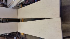
Lastly, the Birch I want to use: Some is authentic BB, and the other is Chinese birch from Menards..
What side looks better? The marked side or the clean?
LIke I said, opinion..see pics...
I tested a couple Dayton Reference Series drivers for my line-source mid-bass tower. One a 7" and the other an 8".
To my ears, the 7" was a little "quicker" than the 8", but that's not necessarily what I'm after...I happen to like a softer, less punchy sound, plus the 8s produce a lot more SPL due to sheer size of the driver..
So question one: Unless there is an (unbeknownst to me) reason why I should choose the 7 over the 8, what would that reason be?
Also, the resistor values in bolserst's post from 4/12/17 now show up in my computer's simulation.
OK to go ahead and order these values? Side note: I'm gonna run these values using resistors in series so they don't fail due to wattage of the system..
Lastly, the Birch I want to use: Some is authentic BB, and the other is Chinese birch from Menards..
What side looks better? The marked side or the clean?
LIke I said, opinion..see pics...
Attachments

Hi,
do You intend to use the basses in CB or Dipole casings?
The 7" do sound considerably more precise and alot more punchier in a Dipole compared to the 8", especially when You bandwidth limit them them down to ~50Hz.
Equalizing down to 35Hz -which is a sensitive limit for an array of drivers of this size- softens the sound a bit and could be sufficient in smaller rooms.
But it just adds more frequency range ... only contour, not slam.
The 8", equalized down to 25Hz, add more weight and recognizable depth .... as long as the listening room is not too large.
The appearance of a 7"er tower is slimmer, more elegant and used in a dipole casing the upper bandwidth limit is higher due to the smaller cabinet dimensions.
This could make the xover design a bit easier.
If You intend to 'upgrade' with a subwoofer now or later, the 7"ers crossed over around 50-60Hz would be my recommendation.
The apparent 'speed' and attac of a dipole array using the Daytons 7" is far ahead of what common speakers are capable of.
First time listeners always were surprised where I'd hidden the warp-drive and a few even needed a couple of tracks to accommodate 😀
But putting on a drum track always and instantly cleared the Q what sounds true.
And finally ... the 7"ers do cost less 😉
jauu
Calvin
Putting them in a dipole, baffle around 10" wide 60" high.
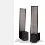
Already have the sub, it's the infinite baffle manifold pictured upthread, made with 4 Sundown (Stereo Integrity) 18s.
So far, I only have 2-7s and 2-8s, but will order the rest after I run some tests on them.
There is not much difference between the 7 and 8 and their respective Le measurements (a gauge of speed according to adire audio)
The 7 is.45@1kHz and the 8 is .49, is there another test I can run to determine 'speed'?
Anyway, late for work..
I meant to add a link to some postings on diyAudio that preceded the blog which included some example plots to help visualize what happens to the response when moving resistance from the secondary to primary side of a “real” transformer having leakage inductance and winding capacitance. See Posts #84 thru #92 here:… CharlieM recently added some discussion on this topic on his blog, about 1/3 way down the page here:
Jazzman's DIY Electrostatic Loudspeaker Page... I attached a copy of the relevant section.
http://www.diyaudio.com/forums/plan...-esl-simulator-esl_seg_ui-10.html#post4911044
If it was me I would probably hold off ordering there resistors until your stators are complete, just in case something changes in your plan as far as dimensions, or D/S spacing. Good plan to use series of resistors to share the wattage/voltage, especially for the first few segments. Once you get to the outer segments, you can shift to using single resistors if you desire. See example plots of worst case scenario wattage and voltage requirements for CharlieM’s and Bengel’s ESLs here:…the resistor values in bolserst's post from 4/12/17 now show up in my computer's simulation. OK to go ahead and order these values? Side note: I'm gonna run these values using resistors in series so they don't fail due to wattage of the system...
http://www.diyaudio.com/forums/plan...segmented-wire-stator-esl-11.html#post4201455
http://www.diyaudio.com/forums/planars-exotics/286989-about-take-esl-plunge-19.html#post4673746
I can run something similar for your setup if you tell me what transformer step-up ratio and amplifier output level to use.
- Status
- Not open for further replies.
- Home
- Loudspeakers
- Planars & Exotics
- The Thrill is Gone.. S-ESL Build