Well in order to make a fair comparison: first off all filters to be compared must have fully identical pass/stopband characteristics, that is with 0,5 dB or so.
To achieve that (=3 different topologies with identical characteristcs) is already a very hard act, given the component sensitivities of both active and passive filter topologies.
Good luck,
Eelco
To achieve that (=3 different topologies with identical characteristcs) is already a very hard act, given the component sensitivities of both active and passive filter topologies.
Good luck,
Eelco
When one is looking for the one that "sounds best" much of that other stuff will not be as important as one would think.
None of them will be exact.
I am going for a Q of .5 since all of them can do that and will try to get the cutoffs as close as I can but the exactness of the slopes is not that important for audio in my opinion.
I am looking more for artifacts left by the different filters more than some absolute specific slope. I will rest assured that none of them will be perfect.
I will fiddle around with component values to get as close to "right" as possible but I will not go to any trouble trying to make them all look the same on a graph before listening to them.
At this point I do tend to suspect the crudest one will be the best sounding, the rcrc, but I have to give the others a try.
The comments in Boden's link may well explain why high open loop gain was important when choosing an opamp for the FDNR circuit. Though the discussion seems to be more around notch filters???
The GIC on the high pass simulates (and measures in real life) exactly like the equivalent passive circuit with ideal capacitors and inductors would measure.
The FDNR in the low pass circuit also simulates (and measures in real life) exactly like the equivalent passive circuit with ideal caps and inductors would measure UP TO A POINT. It does run out of steam, but it is already around 80db down by the time it runs out of steam and for me that is good enough.
Now the challenge with comparing the RCRC with the active implementation is that a passive RCRC is not going to be the same as a standard LC. I could probably sim it in spice and tweak the values in the FDNR to match as closely the curve in the RCRC as possible. That would be the true test for quality comparisons.
If you are happy with that Rick, then I think the flexibility that the synergy gives in setting what ever electrical slopes you want (within the limit of what can be done with LCL) should allow you to tailor the curves to get exactly the acoustic slope you want/need. If you do the same with the high pass, and get good phase matching in the crossover region, then you may reach another level of satisfaction! 🙂
Tony.
Last edited:
I may (otherwise known as you can expect it) ask you for this assistance!
I guess in this world of compromise I do not expect the filters to behave the SAME WAY which is why I want to try all of the approaches and hear which one sounds the best.
Sometimes the warts hurt and sometimes they help. You never know.
I want the SYNERGY to be the best because of the flexibility it allows but each system has its own set of foibles so the trick is to see which sets of foibles work best which each other. That's what makes this hobby interesting.
Take care,
Hi Rick, the boards are on their way 🙂 Attached is the BOM I used with part-numbers from RS RS Australia | World Leading Distributor of Electronics, Electromechanical and Industrial Components and Element14/farnel http://au.element14.com/
I tend to be a bit obsessive about choosing components (http://www.diyaudio.com/forums/blogs/wintermute/119-problem-wanting-get-best-performance.html) so thought I'd let you see what I used.
You'll only need the components in the LP section of the filter. I'll double check which ones. Also I'll check which are the resistors that you will need to change for your slopes (will only be two and the other one will be a shunt as mine was third order).
I'm going to be pre-disposed for a while and may not have a chance to do any sims before you get the boards, so please be patient! 😉 If you can post a pic of the RCRC setup that would be good (I've not done passive RC filters before, I'm assuming it is R in series C shunt). I'm also assuming the buffers have almost infinite input impedance and low output impedance, I'll probably just sim it with some LM4562's configured as buffers which should be a good enough approximation for getting the slope.
edit: I've attached an annotated schematic of the LP section. One thing you may need to add is an output resistor to ground, if you do probably a 1meg would be ok, it depends on the input of your buffer. Let me know what it is so I can sim as too low an impedance may change the slopes.
Tony.
Attachments
Last edited:
Just thought I would give an update on my low pass adventure.
Have not got the boards yet.
BUT I did get the inductors from CARNHILL so I replaced the RCRC with an LC filter with a Q approx .7 - improved my linearity in the crossover region. I do not hear anything wrong with them (yet?). Silent - these do not pick up noise.
CARNHILL is part of the same group that includes PENNY & GILES so the stuff must be good? That is what I convinced myself when I bought them.
If I can do it with passive devices, still between two buffers, that is my default.
On the other side of the crossover - the high pass - I now realize why the crossover region was so depressed after seeing what happened with the low pass. I have two first order filters in cascade which results in a super low Q.
I will, instead of the first order crossover at the speaker, now use a second order tuned for a Q over 1 to get a total Q around .6 to .7.
Will let you know ...
When you cascade active filters you must put the order: lowest Q first and highest Q last...................... I have two first order filters in cascade which results in a super low Q.
I will, instead of the first order crossover at the speaker, now use a second order tuned for a Q over 1 to get a total Q around .6 to .7...........
This affects the way it overloads, or doesn't.
I thought it would be understood that there is a cap at the input of the amplifier and the second order (peaking) crossover at the speaker. My amp has to have both input and output caps so why not put them to best use? The output caps have been moved from the amplifier to the speaker to make adjustment of value easier.
I was worried that peaking crossover would sound weird. It measures so much flatter (almost magical to this audio dilettante) and sounds that way. Hoping I am not hearing what I see. Only time will tell on that.
I was worried that peaking crossover would sound weird. It measures so much flatter (almost magical to this audio dilettante) and sounds that way. Hoping I am not hearing what I see. Only time will tell on that.
Hi Rick, the estimate of 5 days for delivery of the boards seems to have been way off! From the tracking it appears to have sat in the post office where I dropped it off for about 5 days before it even left the country 🙁 Showing as arrived in the US since Sat so hopefully you should have it soon.
Could you post your LC setup including input impedance of the buffer following it and I can simulate that to get some values for the synergy.
Tony.
Could you post your LC setup including input impedance of the buffer following it and I can simulate that to get some values for the synergy.
Tony.
Don't worry about that! Post offices seem to share that lackadaisical attitude, national identity notwithstanding. I did not expect instant delivery.
So here is what I am doing.
For low pass:
Buffer spec - the complementary Pass buffer with the 2SK170/2SJ74 -
input resistor - 100K
output resistor - 220K
The filter:
4000R series resistor - CARNHILL inductor measured .9950H - .0125 uF to ground,
This is placed between two identical buffers
For high pass:
.02322 uf in the input cap position of a FIRST WATT SIT1 - output caps removed and placed at the loudspeaker with the following filter - in series:
24 uF to 4 mH choke (negligible DCr - less than .1 ohm in parallel- 4R Duelund resistor in series with 50 ohms in parallel with the driver.
Boards came in today.
Good thing I got two. I thought they were "stereo" boards!
One they got going they made it here fast.
Thanks and take care,
Good thing I got two. I thought they were "stereo" boards!
One they got going they made it here fast.
Thanks and take care,
Cool I'll try and get a sim done today. Back to work and will be busy! Big cutover this weekend.
I asssumed you needed stereo so two boards was allways the plan 🙂 I made the boards mono to keep within the 10cm X 10cm limit of the prototyping house good value boards 🙂
Tony.
I asssumed you needed stereo so two boards was allways the plan 🙂 I made the boards mono to keep within the 10cm X 10cm limit of the prototyping house good value boards 🙂
Tony.
Last edited:
No need to rush!
I will change something.
Any idea which is the better way to do the low pass? With the series resistor ahead of the choke or a resistor and capacitor in parallel with the driver?
With the former you need a (as an example) 4K resistor and with the latter 2K. Would either one have a greater insertion loss than the other?
Take care,
Hmmm, I thought when you said you were getting some coils you would do a standard LC ie coil in series, Cap shunting. I've not done any passive line level crossovers before (which are RC as far as I know). What I do know about doing proper LC's is that they are completely dependent on the input impedance of the next stage, but that's about it.... could you post a circuit diagram, I think I'm missing something 🙂
Tony.
Tony.
OK I've gone back and looked at your previous post and see you are doing LC but with added series resistance. I'll sim it and see what it does 🙂
Tony.
Tony.
Hi Rick, I've simulated what I think you have (using DCB1 minimal buffers rather than the 2sk70/2sj74 buffer) For the transfer function, I don't believe this will make any difference, if I was simulating distortion then it would matter.
The filter seems to have quite severe peaking... What is your intended crossover frequency? Increasing the 4K resistor drops the peaking down.
I was able to make a passive circuit that will translate easily to the synergy that matches pretty much exactly. The sim of the Synergy implementation is a little off, but what I found was that in reality the actual implemented circuit behaves exactly like the simulated passive circuit, so I would say you could use these values to get pretty much exactly the response of your LC circuit.
The big question is though, is my sim of the LC right, and if it is, is that what you actually want! 🙂
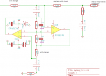
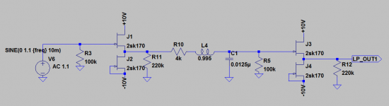
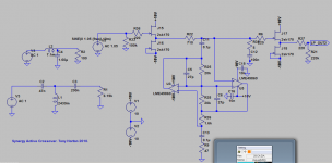
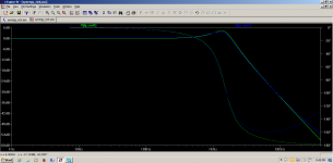
Attached pics: 1st is the circuit that I simmed to represent your filter. 2nd is the passive network (ignore the high pass) and the synergy implementation to match it, that matches the response of the simmed LC network.
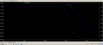
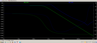
Third is the response of the simmed LC (green) and of the passive circuit Blue. as you can see a pretty good correlation.
Fourth is the response of the simmed LC (green) and of the synergy (blue). Note that as mentioned in reality the implementation of the synergy matches the passive circuit in the sim up to the point where the phase starts to head up again (that really does do that). The level and slope match very well through the entire crossover region in real life. I'm not sure why in the sim it goes a bit off.
Tony.
The filter seems to have quite severe peaking... What is your intended crossover frequency? Increasing the 4K resistor drops the peaking down.
I was able to make a passive circuit that will translate easily to the synergy that matches pretty much exactly. The sim of the Synergy implementation is a little off, but what I found was that in reality the actual implemented circuit behaves exactly like the simulated passive circuit, so I would say you could use these values to get pretty much exactly the response of your LC circuit.
The big question is though, is my sim of the LC right, and if it is, is that what you actually want! 🙂
Attached pics: 1st is the circuit that I simmed to represent your filter. 2nd is the passive network (ignore the high pass) and the synergy implementation to match it, that matches the response of the simmed LC network.
Third is the response of the simmed LC (green) and of the passive circuit Blue. as you can see a pretty good correlation.
Fourth is the response of the simmed LC (green) and of the synergy (blue). Note that as mentioned in reality the implementation of the synergy matches the passive circuit in the sim up to the point where the phase starts to head up again (that really does do that). The level and slope match very well through the entire crossover region in real life. I'm not sure why in the sim it goes a bit off.
Tony.
Attachments
Last edited:
What you drew is what I have done.
Using the formulas here: RLC Low-Pass Filter Design Tool
It predicts a Q of .705 at an Fc of 450 hz.
I am just looking at room response so the peaking may be advantageous in that respect but it was not intentional. I do not see peaking but then it is blended in with everything else that is going on.
I would have thought the buffers more benign or this fellow's calculator is not accurate.
Very interesting.
Addition: I will not be disappointed if SYNERGY does a superior job!
Second addition: could you recommend values I use based upon your sims for Q 0f .7 and an Fc of 450 Hz.?
Last edited:
The filter:
4000R series resistor - CARNHILL inductor measured .9950H - .0125 uF to ground,
I see the problem! 🙂 That should have been 0.125uF 😉
Response with correct cap value. Green being correct. The calculator looks fine.
I'll redo the sim for the Synergy but it might not be till Sunday depending on how I go with the work I've got on.
Tony.
Attachments
Sorry about that.
Should have looked again before posting.
Relieved to hear there is correlation!
Ordering parts for the boards today.
THANKS for your help and proofreading!
Please do not get in a rush with the sims.
Do you have an opinion as to whether there would be any difference between using a 4K resistor in series versus a 2K resistor to ground in parallel with the capacitor?
Take care,
Last edited:
- Status
- Not open for further replies.
- Home
- Source & Line
- Analog Line Level
- The Synergy "Active" Crossover