Awesome! Thanks Ben and El Reino. I was hoping it's something approachable. And it looks very doable.
Ben the set-up you linked looks very simple sound card, software, and a few resistors. It almost looks too easy. Is it really that easy to setup?
Jeffrey
Ben the set-up you linked looks very simple sound card, software, and a few resistors. It almost looks too easy. Is it really that easy to setup?
Jeffrey
Yes, it is easy. I also built a resistor network voltage divider to attenuate the output from the amplifier under test:
https://www.akitika.com/documents/BuildingTheAttenuatorRev4.pdf
Also for the load resistor, be sure to mount it on a heat sink.
https://www.akitika.com/documents/BuildingTheAttenuatorRev4.pdf
Also for the load resistor, be sure to mount it on a heat sink.
As Ben says it works !!!
I implemented my system with the start of sheltering at home in CA
Great tool for the diy world
Best
Bob
I implemented my system with the start of sheltering at home in CA
Great tool for the diy world
Best
Bob
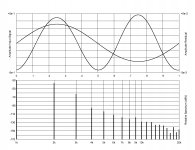
Here are left and right channels, speaker out between 0R3 and 0R3, Vgs=36.5V, Iq=2.3A:
Silly ZM
I forgot to thank you for these

DiAna will show the distortion phase.
Some info at DiAna
Download DiAna 1.58.9 at Index of /diana/
Contact Edmond Stuart for the password DiAna, a software Distortion Analyzer
I have to stop my antivirus software (AVG) before using DiAna.
Some info at DiAna
Download DiAna 1.58.9 at Index of /diana/
Contact Edmond Stuart for the password DiAna, a software Distortion Analyzer
I have to stop my antivirus software (AVG) before using DiAna.
DiAna will show the distortion phase.
Some info at DiAna
Download DiAna 1.58.9 at Index of /diana/
Contact Edmond Stuart for the password DiAna, a software Distortion Analyzer
I have to stop my antivirus software (AVG) before using DiAna.
Thank´s itsmee for tip
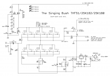
SIT Singing Bush startup procedure
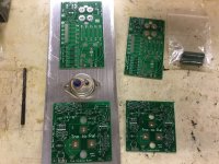
OK, here it is, procedure for Cheerleaders Girliez and us, Greedy Boyz; look at enclosed pics
!! Note - when said simply - "measure" , that means - referenced to GND, so black probe on GND ; when said measure "across", that means both probes across one part ....... though , I believe Greedy Boyz building this one are having some mileage already .......
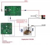
-for start , there is a wire connecting Mu Mosfet source side and SIT Drain; as written on pic - OMIT that wire for start; whichever side of it you didn't connect, put some isolation, to avoid BigBadaBoom
-wise to put some slow fuse in 60V line - say that 4A Slow is good one; be creative how you're going to do that, and of course you are going to remove it after entire setting and settling fun
-just one setting at MuStage pcb - set P1 (10K) to max value - be creative how to confirm that with Ohmmeter
/////////
Now - up to SIT pcb :
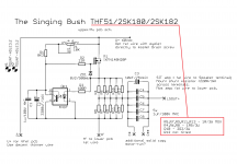
-look at attached schm - be sure that trimpot P1 is set to max, confirm with probes across R8 , need to be slightly bellow 30R
-P2 -the same - set it to max reading across R10
- find some beaten IC socket with those tubular golden thingie pins, heat plastic a little and force 4 pins out ; ok - force more of them, but you'll need 4 of those, unbroken ones
-use a pair of these 1-pin sockets and solder them first on pcb in place of R9, then mount R9 in sockets , solder R9 in sockets - that will give you nice and firm test points , for setting Iq of buffer itself
now - regular anti-stress and anti-fire in the house measures - everything is mounted as need to be - did I told you that doing one channel by one is cunning? be creative how to arrange that
put probes of DCmVmeter across finely done R9, range to whatever is bigger than 20mV
- fire up that channel ; LEDs are lit!!, so most probably IRF is prepared to give some juice for input JFet buffer
-twiddle P1 to get 20mV reading on meter, which means buffer Iq is set to 20mA, which is enough juice even for controlof BigHonkinSIT
-just for fun, find trace where you can check what's voltage at IRF source ( that's positive rail for buffer) - there is plenty of possibly empty pads for T092 JFets ; expect aroundish 7V there
-just for fun, check what voltage you can set twiddling with P2 - you can use SIT Gate pad for red probe ; so , you confirmed that twiddling with P2 is giving a change, now set it to max neg voltage and be done
-power Off the entire Shebang, do the same procedure with other channel
////////////////////
- now , connect properly that Violet wire which was non existent in first part of procedure
- one Voltmeter at SIT drain, set to MuchoVolts - for observing/setting OUTPUT NODE potential
- second Voltmeter (2V range) across any of R5,R7,R9,R11,R13 on Mu pcb - for observing/setting Iq
-power ON the Shebang, observe that you don't have some nasty figures across Iq meter - for instance - 3A across 0R2 means 0V6 ; everything under for now is OK, everything above , say , 0V75 is alarming ; it practically needs to be 0 for start
**********NOW! - you need to iteratively fiddle with:
-P1 on Mu ,to set exact Iq of, say , 2A3, which is 460mV across Iq meter,
-P2 on SIT pcb , to get magic number of 34-37V at SIT Drain
when you achieve that , well - when you're in 15% ballpark, with heatsinks approaching temp equilibrium, you can leave it and proceed with same second part od procedure with second channel
when you are done with that , repeat second part of procedure with both channels, this time trying to pinpoint it where intended (2A3 and 34-37V) in temp equilibrium, lids closed
Addendum for few lucky bstrdz, having 2SK77B on hand :
-everything the same , except all 3W resistors on Mu pcb are 1R
-magic numbers are those from Papa's BAF2015 schematic - Iq is 3A2 ( 640mV across 0R2 group) and approx Urail/2 at SIT Drain
good luck , and Thanks For All The Fish
IMPORTANT!!!! - do not forget to connect 15Vac for bias part , in any moment
OK, here it is, procedure for Cheerleaders Girliez and us, Greedy Boyz; look at enclosed pics
!! Note - when said simply - "measure" , that means - referenced to GND, so black probe on GND ; when said measure "across", that means both probes across one part ....... though , I believe Greedy Boyz building this one are having some mileage already .......
-for start , there is a wire connecting Mu Mosfet source side and SIT Drain; as written on pic - OMIT that wire for start; whichever side of it you didn't connect, put some isolation, to avoid BigBadaBoom
-wise to put some slow fuse in 60V line - say that 4A Slow is good one; be creative how you're going to do that, and of course you are going to remove it after entire setting and settling fun
-just one setting at MuStage pcb - set P1 (10K) to max value - be creative how to confirm that with Ohmmeter
/////////
Now - up to SIT pcb :
-look at attached schm - be sure that trimpot P1 is set to max, confirm with probes across R8 , need to be slightly bellow 30R
-P2 -the same - set it to max reading across R10
- find some beaten IC socket with those tubular golden thingie pins, heat plastic a little and force 4 pins out ; ok - force more of them, but you'll need 4 of those, unbroken ones
-use a pair of these 1-pin sockets and solder them first on pcb in place of R9, then mount R9 in sockets , solder R9 in sockets - that will give you nice and firm test points , for setting Iq of buffer itself
now - regular anti-stress and anti-fire in the house measures - everything is mounted as need to be - did I told you that doing one channel by one is cunning? be creative how to arrange that
put probes of DCmVmeter across finely done R9, range to whatever is bigger than 20mV
- fire up that channel ; LEDs are lit!!, so most probably IRF is prepared to give some juice for input JFet buffer
-twiddle P1 to get 20mV reading on meter, which means buffer Iq is set to 20mA, which is enough juice even for controlof BigHonkinSIT
-just for fun, find trace where you can check what's voltage at IRF source ( that's positive rail for buffer) - there is plenty of possibly empty pads for T092 JFets ; expect aroundish 7V there
-just for fun, check what voltage you can set twiddling with P2 - you can use SIT Gate pad for red probe ; so , you confirmed that twiddling with P2 is giving a change, now set it to max neg voltage and be done
-power Off the entire Shebang, do the same procedure with other channel
////////////////////
- now , connect properly that Violet wire which was non existent in first part of procedure
- one Voltmeter at SIT drain, set to MuchoVolts - for observing/setting OUTPUT NODE potential
- second Voltmeter (2V range) across any of R5,R7,R9,R11,R13 on Mu pcb - for observing/setting Iq
-power ON the Shebang, observe that you don't have some nasty figures across Iq meter - for instance - 3A across 0R2 means 0V6 ; everything under for now is OK, everything above , say , 0V75 is alarming ; it practically needs to be 0 for start
**********NOW! - you need to iteratively fiddle with:
-P1 on Mu ,to set exact Iq of, say , 2A3, which is 460mV across Iq meter,
-P2 on SIT pcb , to get magic number of 34-37V at SIT Drain
when you achieve that , well - when you're in 15% ballpark, with heatsinks approaching temp equilibrium, you can leave it and proceed with same second part od procedure with second channel
when you are done with that , repeat second part of procedure with both channels, this time trying to pinpoint it where intended (2A3 and 34-37V) in temp equilibrium, lids closed
Addendum for few lucky bstrdz, having 2SK77B on hand :
-everything the same , except all 3W resistors on Mu pcb are 1R
-magic numbers are those from Papa's BAF2015 schematic - Iq is 3A2 ( 640mV across 0R2 group) and approx Urail/2 at SIT Drain
good luck , and Thanks For All The Fish
IMPORTANT!!!! - do not forget to connect 15Vac for bias part , in any moment
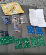
Attachments
Last edited:
OK, here it is.......
Boyz, ya happy with short and sweet tutorial?
will do tomorrow same one, for Schade Singing Bush
Boyz, ya happy with short and sweet tutorial?
will do tomorrow same one, for Schade Singing Bush
Superb
Thank you ZM
Boyz, ya happy with short and sweet tutorial?
will do tomorrow same one, for Schade Singing Bush
So far it's awesome😀
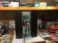
First mono block up and running.
(Fugly!)/2
🙂
have holes in base plate , between htsnk ribs?
(btw. Mighty Moi never won any Audio Society Prize
 )
)- Home
- Amplifiers
- Pass Labs
- The Singing Bush Tips 'n' Tricks