all 4 are 024 - 025 hfe putting on multimeter as In datasheet pin 1 collecor
here what I use http://www.farnell.com/datasheets/1693072.pdf
If I swap transistor and put It on multimeter then I got hfe 345
here what I use http://www.farnell.com/datasheets/1693072.pdf
If I swap transistor and put It on multimeter then I got hfe 345
May I ask a question, did you listen to the Shiga before and after the cap trials? I am curious what did that translate into in terms of subjective listening, in this case, of your ears.
I remember seeing a picture that you posted in the Shiga thread some time ago that you had a somewhat long lead to the circuit, and the sense lines were not on the PCB and were half way shorted by a connector. Have you made a change since then? Maybe posting a picture here will also be helpful.
I remember seeing a picture that you posted in the Shiga thread some time ago that you had a somewhat long lead to the circuit, and the sense lines were not on the PCB and were half way shorted by a connector. Have you made a change since then? Maybe posting a picture here will also be helpful.
I would like an LTSpice spice circuit for the SSLV 1.1 BIB positive mosfet regulator? I searched but did not find one, but this is a very large thread.
Thanks
Jim
Thanks
Jim
thank you Salas
I used It opposite - c b e - like Is shown on posted datasheet
Maybe a datasheet error. Possibly the source of your problems if an error indeed and not a peculiar version of the type which is unlikely.
I would like an LTSpice spice circuit for the SSLV 1.1 BIB positive mosfet regulator? I searched but did not find one, but this is a very large thread.
Thanks
Jim
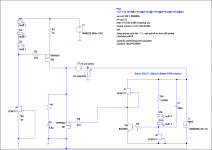
You got to construct it from this picture because as a file has no script models, refers to my hard disk libraries. *The K117s are GR for IDSS. **The open loop analysis setup for which the virtual sources correct positions and plot function I include in the pic is based on Michael Tian's and colleagues paper. You may Google it.
Attachments
Thanks Salas
I have it working now. I have to admit that my version had an upside down mosfet, now spotted and corrected thanks to you.
The probe is new to me, figuring it out should keep me entertained for sometime.
Jim
I have it working now. I have to admit that my version had an upside down mosfet, now spotted and corrected thanks to you.
The probe is new to me, figuring it out should keep me entertained for sometime.
Jim
The prb=0 is for when to energize the main voltage source and the load current source for small signal AC=1 and go looking for Z domain.
Maybe a datasheet error. Possibly the source of your problems if an error indeed and not a peculiar version of the type which is unlikely.
I turned arround transistors and voltage at output became 22 V
thank you Salas
then I tried to replace IRF740 used as output device and broke another STP55 - don't know If It was overheated or static blown - be carefukk with STP55 handling
the next STP55 change was done using premounted on heatsink and It was OK but the output has lowered to 14 V and the STP55NF Vgs Is 1.90 V
Is It normal a change from one type of FET to other to lead to 7 V decrease of output voltage
Can you take a scope picture of its output on dummy load resistor for nominal WaveIO current at 10nS/2mV div and shortest probe ground fixture possible? I want to observe something, thanks.
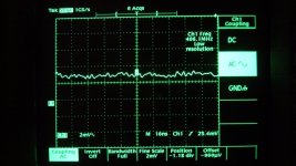
Here is results.
Sorry, I do not understand how to measure in low noise environment.
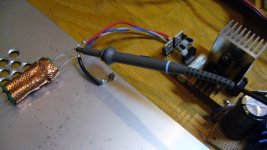
Load is 13.6ohm with copper foil, and aluminium boad on floor.
Probe is putting on close to terminals as possible. Probe is set on X10. So the vertical axis is read in 10 times.
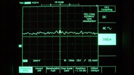
First photo shows output of Reflektor running. Second is GND noise.
Attachments
As I had explained the VGS is directly deciding the current bias in the mirror. I=VGS/1KI turned arround transistors and voltage at output became 22 V
thank you Salas
then I tried to replace IRF740 used as output device and broke another STP55 - don't know If It was overheated or static blown - be carefukk with STP55 handling
the next STP55 change was done using premounted on heatsink and It was OK but the output has lowered to 14 V and the STP55NF Vgs Is 1.90 V
Is It normal a change from one type of FET to other to lead to 7 V decrease of output voltage
That current is what gets converted in your passive Vref. So yes, its absolutely normal to lose voltage with less VGS type and same Ref resistors. Put a Zener or LEDS string for Vref if you want same results with many types and better drift. The ref filter capacitor is big enough for cleaning any ref.
Here is results.
Sorry, I do not understand how to measure in low noise environment.
Load is 13.6ohm with copper foil, and aluminium boad on floor.
Probe is putting on close to terminals as possible. Probe is set on X10. So the vertical axis is read in 10 times.
First photo shows output of Reflektor running. Second is GND noise.
Hi Kazuo
Better set the probe at 1X and turn the Tek TDS scope's 20MHZ bandwidth limit "ON".
Hi Salas,
I am a bit lost between more than 6000 posts of this topic. I would like to build 2 regulators:
- one symmetric one for RIAA corrector (MM type) -> +-15V/30mA,
- on for my DAC, +-5V/0.5A
Which versions of SSLVSR you recommend to be made for above applications?
I am a bit lost between more than 6000 posts of this topic. I would like to build 2 regulators:
- one symmetric one for RIAA corrector (MM type) -> +-15V/30mA,
- on for my DAC, +-5V/0.5A
Which versions of SSLVSR you recommend to be made for above applications?
I have a working 5v SSLV1 and accidentally sorted around Q303. All LEDs continue to glow, however I have .78V at the load now and I observe D305 and d306 LEDs continue to glow for a minute after I switch off the regulator something that did not happen in the past. Any hint on parts to replace or measure?
- Status
- Not open for further replies.
- Home
- Amplifiers
- Power Supplies
- The simplistic Salas low voltage shunt regulator