Thank you Andrew, hour advice helped me to tackle down the problem.
The CCS didn´t work.
It was the weirdest mistake actually: A small metal fibre (I guess from a desoldering litz) was trapped under one of the CCS-LEDs and shorting something. 🙄
The CCS didn´t work.
It was the weirdest mistake actually: A small metal fibre (I guess from a desoldering litz) was trapped under one of the CCS-LEDs and shorting something. 🙄
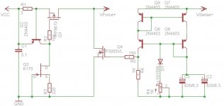
A Salas style Shunt regulator is two bits of circuit/
A CCS and a voltage controlled current load.
The combination results in a controlled output voltage.
You can build and use the two parts separately. It just that here they are integrated into the same PCB.
A CCS and a voltage controlled current load.
The combination results in a controlled output voltage.
You can build and use the two parts separately. It just that here they are integrated into the same PCB.
Hi Salas,
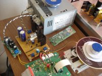
Just got my second wire-2-wire Bib up and running, this one is to power the digital 5V section of the new Shigaclone. It works great. Picture attached.
Is there a version of the reflector for 5V somewhere in this long thread? I searched but failed to find one. Do you mind to point me to the right direction?
I am curious to compare the Bib and the Reflector.
Thanks!!
Attachments
Looking good Fred, congratulations! For Reflektor very low voltage make a search for member's Kazuo Ozawa posts. He had shown practical builds and values for 5V and below. He had tested Logic Level Mosfets results that allow it working such low as I had suggested. Interesting comments about semis types and Zobel termination values there too.
Thanks, Salas, found the schema.
Will have to hunt for some parts before I can start.
What kind of wattage needed to the 560R resistors?
I suppose the current passing through the mirrors won't be that big. Is it a right assumption?
Thanks again!!
Will have to hunt for some parts before I can start.
What kind of wattage needed to the 560R resistors?
I suppose the current passing through the mirrors won't be that big. Is it a right assumption?
Thanks again!!
salas what other fet from here JFET | Junction Gate FET | Farnell Italia | Results can I use in place of k170/k117/bf245 for the
reflektor(3.3V and 5V)
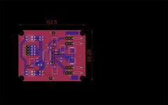
I want to start prototyping the board...
reflektor(3.3V and 5V)
I want to start prototyping the board...
that would be a 500R - 1k resistor?
edit : nope... was looking at the wrong table
edit : nope... was looking at the wrong table
Last edited:
http://www.fairchildsemi.com/ds/MM/MMBFJ113.pdf
at which table do I have to look to find needed Ugs for Id 2ma , cause sincerely I am looking for a while at the datasheet and didn`t manage to figure it out 🙁
at which table do I have to look to find needed Ugs for Id 2ma , cause sincerely I am looking for a while at the datasheet and didn`t manage to figure it out 🙁
Transfer characteristics chart. But its typical when samples vary. You just grab 2 Jfets, you put them on a bread board, you connect a trimmer from S to GND. Then you short the gate to GND. You provide 9V from a battery or more up to what it will be in the particular settings in the reg and you trim to a value for 1.5mA running in our use. You can find out by voltage drop over the VR. Or by hooking a mA meter mode DMM in series. Then you use the VR values for selecting nearer standard resistors to install. Battery (-) stands for GND. (+) goes to D pin.
a little bit over hand...
I already have two breadboard sslv v1( powering my actual breadboard pcm1794) and in each one I have 3 pieces of 2sk170, I think I will put out those, with these I can use same 82R resistor?
I saw that Kon uses on his last versions of the reflektor low value mica on the zobel
I plan to power two pcm1794`s(2x 3.3v , 2x 5v) and one amanero card(3.3v), so in total I would have to do 5ps`s
what values do you recommend for the zobel?
Those in the 1.1 are K117GR normally. If you breadboarded with K170BL use them with 220R or bigger in the Reflektor. Use 1R and 100n down to 33n that Kazuo san likes also.
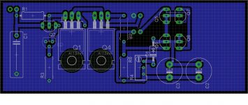
Its wrong to have common ground plane when wanting force and sense. Those two pairs meet at the load only on both ends.
on the pcb side the gnd only surrounds Vsense-
the wires between reflektor and dac will be very short, below 10 cm
for the current mirror bjt`s I paired right Q5Q7 and Q6Q8?
the wires between reflektor and dac will be very short, below 10 cm
for the current mirror bjt`s I paired right Q5Q7 and Q6Q8?
Only q5,7 may be bonded, the pairings are good. Sense and force grounds should be completely separate for any length of wires.
I'd like to use this layout...
Schultzsch, did you alread build this?
Salas, I can see the sensors are isolated (draw att)... So, no problem yah?

Schultzsch, did you alread build this?
Salas, I can see the sensors are isolated (draw att)... So, no problem yah?
- Status
- Not open for further replies.
- Home
- Amplifiers
- Power Supplies
- The simplistic Salas low voltage shunt regulator