Its a juggling act since the available gate drive current reduces, so while the OLG goes up lower in freq due to more voltage drive it also starts falling earlier. That ups Zo before 100kHz and it could be associated with your preference for carbon film. All in conjunction with M2 type, Zobel, & specific active load. Also the phase margin changes so checking with oscope is essential as you mentioned. Its a tolerant topology but tweaking that far without visual test gear is not recommended to novice builders I guess.
Its a juggling act since the available gate drive current reduces, so while the OLG goes up lower in freq due to more voltage drive it also starts falling earlier. That ups Zo before 100kHz and it could be associated with your preference for carbon film. All in conjunction with M2 type, Zobel, & specific active load. Also the phase margin changes so checking with oscope is essential as you mentioned. Its a tolerant topology but tweaking that far without visual test gear is not recommended to novice builders I guess.
Salas thank you for explaining the effects of increasing R5. I am fully aware of the risks involved, but High End audio is often trail and error, and about pushing the limits. Sonically the circuit reaches a level of performance I have not heard before.
Peter
Phew, lots of drawing.
Salas
are these most up to date 1.2R
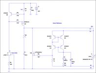
which one you recommend to power with 24 Vdc Ugs preamp
Those were the last, yes. Two Reflektors in floating double polarity arrangement would be easier to implement for layout, are anti ground loop, also absolutely the same for semiconductors between the two polarities. Which can be many similar types. The CFP in the 1.2R can be sensitive and give pain in the making and deployment. I will show you a 24V example ASAP.
Here you are. This can go to 35Vout safely also. Spot on Vo its all about using the proper R8. Or a 10K trimmer. Not best choice for ppm but handy. For finding the right value including current and VF tolerances in a build and then substituting with a good R8 at least. Keep 10V drop over the reg for the 9610 to be on its low capacitive.
Attachments
thank you very much Salas
Is this 24 V reflektor a better choice over BIB for powering UGS V3 pre
regards
Is this 24 V reflektor a better choice over BIB for powering UGS V3 pre
regards
They are both adequate. It takes you combine them with a certain preamp and you choose subjectively which one combination you may prefer.
which one of the BIB, reflektor, 1.2r Is more Independable from wire distance between regulator out and load (25 - 45 cm) and also which one of the three Is more oscilations free than others
There are general precautions that should be the same but probably the Reflektor would be easier to work with and deploy. It has just one driver block doing it all by monitoring current dif.
Salas
I see that In reflektor you have lowered zobel cap to 0.1 from 0.47
Is that a tunning mod based on listening tests - Is regulator stable that way
I see that In reflektor you have lowered zobel cap to 0.1 from 0.47
Is that a tunning mod based on listening tests - Is regulator stable that way
Its bcs there is a lower capacitance (Crss) Mosfet in this example. Same margin. Use a scope in general for verifying or modding any real system build.
Hi
Is there any problem using the BiB boards to feed for example DACs that has local voltage regs on board?
Staffan
Is there any problem using the BiB boards to feed for example DACs that has local voltage regs on board?
Staffan
Hi Staffan,
Yes, take off the local voltage regulator if you want to enjoy all BiB perfomance😉
Felipe
Yes, take off the local voltage regulator if you want to enjoy all BiB perfomance😉
Felipe
Last edited:
Hi Staffan,
Yes, take off the local voltage regulator.
Felipe
Thanks Felipe, but thats not an option on DACs. They need local regs near the source.
/Staffan
Hi
Is there any problem using the BiB boards to feed for example DACs that has local voltage regs on board?
Staffan
They have done it before on vintage AD DAC with TL431 in between and it was not unstable as a system. Each total system has its quirks though and should be checked.
Higher voltage Vin and Vout?
I am in need of a version with Vin of ~ +/- 55 volts and +/- 45 volts Vout.
Has work been done on a version capable of these parameters?
I appreciate all the work that has been to this point!
Thanks.
I am in need of a version with Vin of ~ +/- 55 volts and +/- 45 volts Vout.
Has work been done on a version capable of these parameters?
I appreciate all the work that has been to this point!
Thanks.
Hi, I encountered a problem with my BiB-based reg:
The CCS-LEDs light up, but the Vref LEDs stay dark (2 red LEDs). They are oriented properly and work if I apply external voltage to them.
The output voltage is 0V and the current draw from my lab PSU is not measurable (so below around 10mA), whereas it should draw around 100mA.
Did someone have this behavior before?
I have only a limited amount of FETs, so any educated guesses before I pull out random components are very appreciated 🙂
disconnect the shunt regulator part.Hi, I encountered a problem with my BiB-based reg:
The CCS-LEDs light up, but the Vref LEDs stay dark (2 red LEDs). They are oriented properly and work if I apply external voltage to them.
The output voltage is 0V and the current draw from my lab PSU is not measurable (so below around 10mA), whereas it should draw around 100mA.
Did someone have this behavior before?
I have only a limited amount of FETs, so any educated guesses before I pull out random components are very appreciated 🙂
You then have only the CCS part.
Short the output of the CCS.
Check that the CCS is delivering and controlling the current into the shorted output.
Now insert a dummy resistor, 1r0 or 10r and repeat the CCS test.
The current into the dummy load will be a little bit less than the total current draw. The CCS uses a little bit of current to power itself.
Once you know that the CCS is working, you can put the shunt back into circuit.
For beginners this is the way to build up the Salas reg. Populate just the CCS part and test it. Then populate the shunt part and test it.
disconnect the shunt regulator part.
You then have only the CCS part.
Short the output of the CCS.
Check that the CCS is delivering and controlling the current into the shorted output.
Now insert a dummy resistor, 1r0 or 10r and repeat the CCS test.
The current into the dummy load will be a little bit less than the total current draw. The CCS uses a little bit of current to power itself.
Once you know that the CCS is working, you can put the shunt back into circuit.
Thank you, this is good advice, I´ll try.
- Status
- Not open for further replies.
- Home
- Amplifiers
- Power Supplies
- The simplistic Salas low voltage shunt regulator