Is really there a 100R in the tried circuit? Isn't that a notional initial figure and that one got to be the 16R dummy load in practice? If its really there then its 116R shooting up the output and squeezing the Mosfet. There will simply be no voltage margin for what 300mA can do with that value so to be reachable. Am I missing something?
The 100R is not expected. It should be deleted - only the 16R dummy must be between 9610-drain and Gnd. This could explain the low current, for sure.
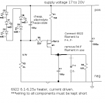
When the 6922 heater is connected, no 100R, and no 16R dummy - just heater between 9610-drain & Gnd.
When the 6922 heater is connected, no 100R, and no 16R dummy - just heater between 9610-drain & Gnd.
We don't need the complication of a "dummy" load.
Use the heater filament. It is just a resistor that heats up.
Use the heater filament. It is just a resistor that heats up.
Its still safety for setting the current not to blow the heater by someone who can't prepare a ballpark Ih reliably.
Its still safety for setting the current not to blow the heater by someone who can't prepare a ballpark Ih reliably.
+1. Do it on the dummy load first merlin, especially with a circuit that's not working exactly right, it's too easy to fry the filament. Nothing wrong with a resistor load.
Hey guys, I am proud to be at Diyaudio forum there is plenty of gentlemans helping newbies like me, I will do last Rod Coleman schematic using the dummy load to be sure all is going on OK & I will report asap.
Last edited:
Measurements:
DCin 15.26V-15.32V
Across dummy load 5.27V
Across R1 4.86V
Across R2 6.24V-6.30V
Across LEDs 8.98V
DCin 15.26V-15.32V
Across dummy load 5.27V
Across R1 4.86V
Across R2 6.24V-6.30V
Across LEDs 8.98V
Yes, it looks like it is working well now. Need to make R1=16.5 to 17R, to get about 0.29A. Can add 1.8R or 2R resistor in series with the 15R.
BTW, the IRF9610 will be dissipating 2 or 3W - just wanted to check you have a little heatsink on it. Run it for an hour, check it's not too hot to touch. THen it will be ready to test on the 6922 heater.
BTW, the IRF9610 will be dissipating 2 or 3W - just wanted to check you have a little heatsink on it. Run it for an hour, check it's not too hot to touch. THen it will be ready to test on the 6922 heater.
300mA through 2r0 is only 180mW. You can use a 500mW or 600mW 2r2 resistor.
Then trim the 2r2 to set the precise current through your heater filament.
2r2 // 22r = 2r0
2r2 // 10r ~ 1r8
You can try trimmer values between 5r6 and 1k till you are happy.
Then trim the 2r2 to set the precise current through your heater filament.
2r2 // 22r = 2r0
2r2 // 10r ~ 1r8
You can try trimmer values between 5r6 and 1k till you are happy.
Last edited:
Thanks Rod, Salas, AndrewT, IKo, etc., for R1 can be 2 resistors 33R 1W in parallel?
Last edited:
Be more confident. Rod gave you range. Since 33/2=16.5 falls in range helps going near until you nail it.😉
Be more confident. Rod gave you range. Since 33/2=16.5 falls in range helps going near until you nail it.😉
Thanks Salas the question was about power 2W?
You say you got nearly 5V across R1. If 0.3A passes that is 1.5W. 2W total will work hot only for quick enough test, and you will have to use 5W in the long run. Also keep legs a bit high so the resistor(s) will not be touching the board.
They will take 15% of total heat only so give it a try and see if it holds well as a combination. Its only testing for now anyway.
- Status
- Not open for further replies.
- Home
- Amplifiers
- Power Supplies
- The simplistic Salas low voltage shunt regulator