I went back into the simulation and looked at some of the heat dissipation issues and realized that I have been underestimating just how hot this thing will get. So, several of my concerns were unfounded. For example at this voltage with 100ma load and 200ma current, the shunt mosfet makes over 14w of heat. And my 1k load resistor makes 3.6w of heat. I'm going to take it back to 130ma of current by changing the 3.3 ohm to 5 ohm and see if that doesn't solve some of voltage rise issues.
Ken
Did you oscope it also? At such Vout, yes be conservative. Run 30-50mA on top of max consumption only.
Did you oscope it also? At such Vout, yes be conservative. Run 30-50mA on top of max consumption only.
Salas,
Not yet, still at the office, have to make money to pay for diyaudio fun.
Ken
Interestingly, just finished the mod on my 37v shunts and the schematic is like your last post for v12r medium positive but I do not have R9 =27r...(The connection is direct)
I am using 10u for vref and 47u // 4u7 film + 0.25r on the output.
Comparing to V12, I lack the ultimate detail but now I have more presence.
Must wait until the caps and solder joints settle before reporting correctly but the tone is quite good.
I am beguinning to understand this version´s results depend on the rest of the system.
in this case, I am using a 0.8mV cart with a 57dB phono so the gain is slightly high producing some thickening.... In this case I prefered the leaner faster presentation of V12.
Let´s wait until it settles and looses the grainy nature.
Might be good but we must consider the size... and the cost.
One thing is that is a capacitors mix and there is the resistor too that ameliorates signatures. Look for 4u7pp caps as in #3200. I got fine results with industrial BC and Wima radials. You guys check if there is better subjectively and let us know. But try industrial caps too to know if there are diminished returns to get with expensive ones or its worthy.
in this case, I am using a 0.8mV cart with a 57dB phono so the gain is slightly high producing some thickening.... In this case I prefered the leaner faster presentation of V12.
Let´s wait until it settles and looses the grainy nature.
That is increased second harmonic you get. Its not the reg as you saw. You can up the source resistor in your stage 1 in the Riaa and throw away some gain is better.
Comparing to V12, I lack the ultimate detail but now I have more presence.
After I listened to lots of records including some Luv N' Haight label's Acid Jazz and Jazz/Funk classics my impression is that everything is in place. I actually feel I get more of everything. Maybe its more compatible on my system and acoustics, don't know.
Salas,
Not yet, still at the office, have to make money to pay for diyaudio fun.
Ken
If it will be a straight DC line on the oscope's AC input setting at your power levels and with your FQPs, you must concentrate on heat I would guess. But try run it as an R also if there are oscillations, maybe the layout will react better on the more resiliently terminated R.
Oscope, no oscillation! With the R1 at 5ohm, a bit less temp, but still have rising output voltage.Did you oscope it also? At such Vout, yes be conservative. Run 30-50mA on top of max consumption only.
Does Vbe of BC546 error amp and Vgs of shunt Mosfet change a little during rising? Does rise stop at a point? Is your K170 GR, BL? do you remember its IDSS? I ask because I have an idea to test.
Q3 the BC546 the Vbe voltage rises and Q4 the Vgs falls, both at what appears to be a similar rate mV/sec as the Vout. The K170 is a BL and I didn't measure the IDSS.Does Vbe of BC546 error amp and Vgs of shunt Mosfet change a little during rising? Does rise stop at a point? Is your K170 GR, BL? do you remember its IDSS? I ask because I have an idea to test.
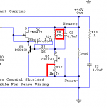
The K170's current is governed by Vbe which is its only voltage VDS, and the trimmer. If Vbe rises incrementally, the current in the fet will rise too and it will be translated in more ref voltage. I propose a test. You short the trimmer, sub a 10k 1W ref resistor for the one connected to K170's drain. So we get its max current possible under Vbe potential and smaller percentage change of it. Also BL pinch off and transfer curves show it will run in more agreeable tempco area if near max since its hot there. You don't know its max current now under Vbe, but with the 10K it will show and you will fix it to 60Vout by tweaking Rd Kohm from there. Lets see if it will be less jumpy.
After I listened to lots of records including some Luv N' Haight label's Acid Jazz and Jazz/Funk classics my impression is that everything is in place. I actually feel I get more of everything. Maybe its more compatible on my system and acoustics, don't know.
In the end I agree with you 🙂
After 24hours burning, the trebble grit whent away (I am using 47u 50v BG) and now everything is in place.
Tone, presence and detail are quite good.
Its a matter of turning the trimmer up and giving it analogous Vin Felipe. Says 45max. Means max out.😉
The K170's current is governed by Vbe which is its only voltage VDS, and the trimmer. If Vbe rises incrementally, the current in the fet will rise too and it will be translated in more ref voltage. I propose a test. You short the trimmer, sub a 10k 1W ref resistor for the one connected to K170's drain. So we get its max current possible under Vbe potential and smaller percentage change of it. Also BL pinch off and transfer curves show it will run in more agreeable tempco area if near max since its hot there. You don't know its max current now under Vbe, but with the 10K it will show and you will fix it to 60Vout by tweaking Rd Kohm from there. Lets see if it will be less jumpy.
Salas,
To make sure I have it right, the Rd you refer to is R8 in the schematic shown, and I've shown a jumper to represent shorting the trimmer - basically taking the source of the K170 to ground. Do I have this right?
Thanks
Ken
Attachments
So I can use this schematics with Vin +7V Vout: Vin 52V?
Wil be enough a trimmer 5K instead 1K?
Salas,
To make sure I have it right, the Rd you refer to is R8 in the schematic shown, and I've shown a jumper to represent shorting the trimmer - basically taking the source of the K170 to ground. Do I have this right?
Thanks
Ken
Yes.
Wil be enough a trimmer 5K instead 1K?
Use a 500R trimmer since it will use the lower range around 200R to run about 1mA on the 47k. You could use the 5k if it has enough turns low to find the rough value after drift settles, and then substitute a resistor, its steadier and more reliable.
So I can I use the schematic only changing 1k trimmer for 500R trimmer & Vin 52V, thank you 🙂
- Status
- Not open for further replies.
- Home
- Amplifiers
- Power Supplies
- The simplistic Salas low voltage shunt regulator