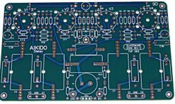
Next Iteration of the layout:
- swapped the resistors around to be very close to the base of BC546B
- added 47uF and 0.01uF decoupling
- increased the width of pcb-traces
Anything else that could use some tweaking on the latest PCB?
I'm definately not so deep into the circuit that I would know which signal pathes should be kept as short as possible and which ones could be longer...
I used MKP10 for 0.01uF and Silmic II for 47uF - better choices?!
As far as I can see, now it looks nice to me, considering the things I could tell. People with PCB expertise must add any further comment.
I have done another slight change to the design:
- moved the two TO247 to the very top of the board for further mounting options - now you don't have to solder them from the bottom side. A further plus is that the 1 ohms resistor can't be accidently touching a pin of the TO247 when not correctly soldered from the bottom.
- moved the mounting holes to all four corners
- added some texts
Board-size is now 76x68mm.
I started working on the negative version. At the moment I'm cross-checking the schematic I made for that version. first design should be ready this evening.
I don't know what PTH means, but I suppose footprints. Which were you thinking about?what about different sets of PTH for c2,c3 of different sizes?
Attachments
Looks well organized by now. Only change the legend about using 2.2u to 10u or 47u into 4.7u to 10u or 47u.
thkl,
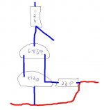
yes, i mean footprint. a bit like in the picture.
for instance, some of the 4,7uf film caps i m using have 27,5mm footprint
PTH=plated through holes, at least in my vocabulary 😉
also, what about adding a resistor+led across the output rails? if it doesnt add noise (maybe?).
yes, i mean footprint. a bit like in the picture.
for instance, some of the 4,7uf film caps i m using have 27,5mm footprint
PTH=plated through holes, at least in my vocabulary 😉
also, what about adding a resistor+led across the output rails? if it doesnt add noise (maybe?).
Attachments
Last edited:
Now it looks better THKL.
I would further move down the big MKP close to the TO247 device for two reasons: 1) how can you fix it if its hole is almost hidden by the cap? 2) too close to heat source (Dale 1W and TO247)
Moreover: enlarge pads size (T092s and resistors 80 mils minimum, big caps 150 mils)
Dale RN65D (1W) requires 17,5mm pitch: seems 15mm only
Can't 2N5459 and 2KK170 close to R 120 ohm be turned differently reducing tracks length?
just my 2C
*That ''Dale 1W'' needs not be 1W. Its just a resistor damping the termination when with a very low loss cap as a film is. Dissipates no appreciable power.
Thanks for all the feedback.
I further refined the design:
- moved the MKP10
- added 27,5mm PTHs
- increased the size of all pads
- changed text on MKPs
Talking about the "power on indicator" led - I am not sure whether it would degrade the circuit quality, but with the LED + resistor you add another consumer not directly covered by remote-sensing.
I leave that question open to salas, but nevertheless I don't really see a place where they could be put on the PCB.
Attachments
Last edited:
Talking about the "power on indicator" led - I am not sure whether it would degrade the circuit quality, but with the LED + resistor you add another consumer not directly covered by remote-sensing.
I leave that question open to salas, but nevertheless I don't really see a place where they could be put on the PCB.
Vin to ground can take a power on LED and its protection resistor, under the 0.01uF I see space, or adopt the BJT cascode with its LED for biasing.
I thought pidesd talked about a LED on the outputs to instantly see whether everything is working...
Adopting the BJT-cascode to LED - would that increase the quality of the circuit? If yes, how would it be done?
Adopting the BJT-cascode to LED - would that increase the quality of the circuit? If yes, how would it be done?
CCS rejection will be the same. One thing is you will not need to sort out 5459s and utilize just another 2SK170BL but only use omnipresent BC550s and 560s, have more Vin max, just a few more components. No LEDS on output, avoid.
yes i thought a led might be useful at the reg s exit. that is why i built the bjt cascode(p190). i just prefer a safety indicator rather than nothing at all, that s the only reason. no fancy led fetichism 🙂
Last edited:
CCS rejection will be the same. One thing is you will not need to sort out 5459s and utilize just another 2SK170BL but only use omnipresent BC550s and 560s, have more Vin max, just a few more components. No LEDS on output, avoid.
What kind of "sorting" are we talking about with the 5459s?
I do not have the luxury of having a large room for hobbyist's work with associated assortment of components.
That is why I triple-check my designs before ordering (add some spare components here and there), but usually in a small time-frame from receiving the PCBs and components, everything will be built (not talking about cases here *g*)
Do you have a shematic handy with LED mod?
Before looking at that I will finish the negtive version and try to finalise both PCBs so they can be ordered and tested - just waiting for some more feedback on what could be improved.
@Massimo: would you advise to use a groundplane "net" (how is that kind of groundplane called, btw?) or leave the ground trace alone?
I thought the groundplane could add some screening, but I'm no analogue wizard...
Would need 7mA or more 5459 for cascoding a 7-9mA BL with 220R degeneration rightly, and that takes Idss measuring and sorting your stash. OK, use the BJT option that has an integrated LED for its bias also, that can double as an ''on'' indicator (at least the CCS will be working if its ''on''). A few more components but it seems easier to you since you will not have to care about selecting BJTs as with FETS.
P.S. I see space for another 1R place in parallel with the output Zobel existing one. Will be good to have a standby second place there. 0.5R combination can go better with 10uF and some loads than 1R for instance. So you can scope or listen for best.
P.S. I see space for another 1R place in parallel with the output Zobel existing one. Will be good to have a standby second place there. 0.5R combination can go better with 10uF and some loads than 1R for instance. So you can scope or listen for best.
Attachments
I added the option of another 1R for output compensation to the PCB.
Furtermore I have finished my first draft of the negative version of the shunt - since the two schematics are similar, the PCBs are similar, too.
Regarding the LED reference BJT-Cascode, I got some more questions. I had a look at page 190 with the "meaner V1.2".
In addition o using the BJTs and LED some resistor values have been changed (27K reference has been changed for instance) and the resistors at the transistor bases are 5,6k instaed of 3,3k.
What is it with those changes?
Attachments
They are changed to 3k3 so you get enough current through the BJT cascode's LED reference, since the example you saw was putting out 46V and you aim for +/-24V. Also the 27K is better for the voltages you aim, so to run the Vref CCS JFET at about the same region. The boards look nice by the way.
I believe grounplane is good for digital circuits only.
Good & necessary😉
- Status
- Not open for further replies.
- Home
- Amplifiers
- Power Supplies
- The simplistic Salas low voltage shunt regulator