No, I don't use any subwoofer, I used the 10nF // 100uF lytic & the effect is not so clear but still seems like sly frecuencies or similar efect like several frecuencies are with overgain, I heard time ago that news & goods capacitors don't need bypass.
If you really need to bypass the silmic, try 2200pF styroflex.... it opens the highs without messing with the mid freq like the 10n you used.
Bypassing is ok in the loudspeaker crossovers or in the output caps but in this case (vref) it is very difficult to implement.
If you want more snap, you can get it with bg on vref 🙂
Bypassing is ok in the loudspeaker crossovers or in the output caps but in this case (vref) it is very difficult to implement.
If you want more snap, you can get it with bg on vref 🙂
Last edited:
Yes possible the styroflex do the trick, few years ago used some TRT Wonder 0,01uF also polysterene exotic foil & the effect was like add a super-tweeter in the system (more: open, air, atmosphere, etc), for the moment I left only the Silmic II working with very good success🙂.
5 volt 2 Amp
Hi to all in this thread. I followed much of the thread because I want to build a 5v 2 Amp regulator. The think is that realy I am confused if it is safe to use to 5 volt due to vgs limitations. So is it OK for 5 volt at that current. Has anyone tryied this way.
Thanks
Hi to all in this thread. I followed much of the thread because I want to build a 5v 2 Amp regulator. The think is that realy I am confused if it is safe to use to 5 volt due to vgs limitations. So is it OK for 5 volt at that current. Has anyone tryied this way.
Thanks
is 2A the maximum output or the CCS current?
These regulators are recommended to have 6 to 10V drop across the CCS.
Let's assume you have ~10V of excess when running on a normal mains voltage and at least 6V when mains is at minimum voltage.
The power dropped in the CCS FET is the CCS current times that 10V. That is going to need a very big heatsink.
Hi to all in this thread. I followed much of the thread because I want to build a 5v 2 Amp regulator. The think is that realy I am confused if it is safe to use to 5 volt due to vgs limitations. So is it OK for 5 volt at that current. Has anyone tryied this way.
Thanks
Used as +/-5V reg in the Dac End project by the dozen. About power, as Andrew said.
What is it for? Single polarity? Some computer card? Merlin has shown one for Buffalo with remote sensing in the recent pages. That one is 1/2 A. Remote sensing is steadily recommended.
Metronome has passed to the "unknow dimension DIY Salas reg"
Voltage 7.5V
Current 442mA
An externally hosted image should be here but it was not working when we last tested it.
Voltage 7.5V
Current 442mA
Salas reg v1.2 lytics 5Volt
Please someone who has a scheme salas reg v1.2 for 5 volt version.

Please someone who has a scheme salas reg v1.2 for 5 volt version.
Page #190 has 1.2 15V example schematics. There is a trimmer for choosing Vout, make that 5k. Use 12V raw DC to feed the reg. Don't adjust less than 5V output. You can use 22uF medium esr output electrolytic capacitor in place of 2.2film + 1R output Zobel network (22uf substituting for both Zobel elements), for better general stability with unknown loads if you don't have means to check oscillations thoroughly.
Page #190 has 1.2 15V example schematics. There is a trimmer for choosing Vout, make that 5k. Use 12V raw DC to feed the reg. Don't adjust less than 5V output. You can use 22uF medium esr output electrolytic capacitor in place of 2.2film + 1R output Zobel network (22uf substituting for both Zobel elements), for better general stability with unknown loads if you don't have means to check oscillations thoroughly.
Thanks for answer Salas. This regulator will supply
AD1865 DAC. What value do you recommend for C2 and type?
Regards
4.7-10uF radial pp box Arcotronics sounded balanced in a build for phono. Maybe there is one like it from Wima, Rifa, Vishay, that you know and like in signal applications. In that position expect known signature if you think you actually differentiate. Another option for bigger easier sound but less in resolution IMHO is 47uF silmic II. Depends on systems. Merlin prefers a lytic there for instance when HiFiNutNut is all the way for very fast film. YMMV.
My first contribution to this thread
Dear Salas,
I have built Salas v1 nice regulator. It is symetric +-24V - it is working properly. I have one question. I can chose shunt MOSFET from whole range of gate to source voltages at 200mA. My opinion is that higher voltage could improve performance since Jfet at input of this Mosfet will be working at e.g. 5.5V Drain to Source instead 3.5V. Is it reasonable or just my fiction?
The 2sk collector load feels very easy already. Its -0.45V pinch off. Did you use remote sensing too? Any pictures? What do you supply with it?
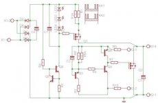
As you can see I tried to avoid to use 12 Led as a reference for plus and minus power supply. I simulated this circuit in MicroCap and the results were nice. I avoided trimer as well. I used two resistors - one trimming the other one. The voltage is stable. It starts at 24.3V and within two minutes it finish at 23.9V in each branch.
I will try to replace my existing power supply in Dispre preamp from PMA (you can find in diyaudio).
I will try to replace my existing power supply in Dispre preamp from PMA (you can find in diyaudio).
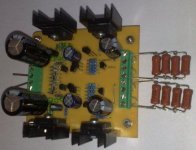
Some another notes to my pictures:
I used IRFP 240/9240
Current source is set to 200mA - there are 2 paralel resistors in source
Heatsinks are below 60 deg
Diodes are BYV26C
Design is made in Eagle software. I can send the design to anybody who would like to have it - of course for free.
At the picture you can see bipolares instead Jfets - it is just because in my database is not nice footprint for 2SK170. At the ready sample there are 2SK170V.
Transformer secondary is 35V after rectification
Eagle works OK for assigning pin compatible BJTs. Good work.
Of course using fixed resistors is good if you know your fixed application. Low ppm good quality resistors as reference and the quality of the capacitive bypass is audible enough.
What is R9,10 in the remote sensing take off points?
Let us know your impressions after listening on Dispre. I hope it will enhance.
- Status
- Not open for further replies.
- Home
- Amplifiers
- Power Supplies
- The simplistic Salas low voltage shunt regulator