Guido,
On the condition that the next time I'm in Bergamo you'll buy me a double espresso 😉
Here you go, I've only made the positive voltage version so far. Just rename the files and remove the ".txt" from the name.
No warranties express or implied....
Ken
Many thanks.
Be careful, (real) italian expresso is veery strong, I doubt that you can afford a double 😉
Here enclosed my attempt. Enjoy!
No warranties neither..
Attachments
Many thanks.
Be careful, (real) italian expresso is veery strong, I doubt that you can afford a double 😉
Here enclosed my attempt. Enjoy!
No warranties neither..
I've had real italian expresso - no problems here... not the burnt bean stuff from that S company.
I've almost finished the negative pcb do you want that as well?
One comment I would make about yours it to make the pads on the big mosfets larger, the holes will take out most if not all the pad. Copy and paste from my file into yours.
Are you planning a v- version? I would be interested if you are.
Ken
!
Finally finished!😀
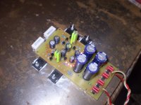
Everything is OK, output voltage when ignition is + /-23.9V DC, after a few minutes the output voltage is + /-23.7V DC, and has not changed in the next half hour to an hour. I have to replace a few resistors with other values, which determine the total current, I have to raise a little current. I used Kingrbight LED L934 Series L934GD (can be used L934GC) and L934EC. In front of the regulator was originally planned to be RCRC filter, will now likely be CRC due to voltage drops, 1800uF - 10ohm - 1800uF. A power transformer 30VA, primary 0V-220V-230V, blind turn, the secondary is 2 * 25V when loaded. I have a problem with network voltage, the current is about 200V AC (to be 220V AC) and it creates problems for me because I have too low a voltage to the regulator Vin-Vout, only about 3-4V DC, when I joined stabilizer voltage difference Vin-Vout is about 7-8V DC.
Here are pictures from the test.
Finally finished!😀
Everything is OK, output voltage when ignition is + /-23.9V DC, after a few minutes the output voltage is + /-23.7V DC, and has not changed in the next half hour to an hour. I have to replace a few resistors with other values, which determine the total current, I have to raise a little current. I used Kingrbight LED L934 Series L934GD (can be used L934GC) and L934EC. In front of the regulator was originally planned to be RCRC filter, will now likely be CRC due to voltage drops, 1800uF - 10ohm - 1800uF. A power transformer 30VA, primary 0V-220V-230V, blind turn, the secondary is 2 * 25V when loaded. I have a problem with network voltage, the current is about 200V AC (to be 220V AC) and it creates problems for me because I have too low a voltage to the regulator Vin-Vout, only about 3-4V DC, when I joined stabilizer voltage difference Vin-Vout is about 7-8V DC.
Here are pictures from the test.
Attachments
Finally finished!😀
Everything is OK, output voltage when ignition is + /-23.9V DC, after a few minutes the output voltage is + /-23.7V DC, and has not changed in the next half hour to an hour. I have to replace a few resistors with other values, which determine the total current, I have to raise a little current. I used Kingrbight LED L934 Series L934GD (can be used L934GC) and L934EC. In front of the regulator was originally planned to be RCRC filter, will now likely be CRC due to voltage drops, 1800uF - 10ohm - 1800uF. A power transformer 30VA, primary 0V-220V-230V, blind turn, the secondary is 2 * 25V when loaded. I have a problem with network voltage, the current is about 200V AC (to be 220V AC) and it creates problems for me because I have too low a voltage to the regulator Vin-Vout, only about 3-4V DC, when I joined stabilizer voltage difference Vin-Vout is about 7-8V DC.
Here are pictures from the test.
Bravo, really have 20V AC less? if yes you have a big problem, I praise your work looks very clean, what about the sounds? what is feeding: a pre-amp, DAC, etc? wich components did you used?
Bravo, really have 20V AC less? if yes you have a big problem, I praise your work looks very clean, what about the sounds? what is feeding: a pre-amp, DAC, etc? wich components did you used?
Yes indeed. Right now I'm measured three-phase voltage, on one phase is 213V AC, 204V AC in the second and the third phase 208V AC. Pre-amp is not completed, it will soon be ready for testing.
Resistors are standard metalfilm 0.6W, United Chemi Con capacitors LXZ 1800uF 50V, Panasonic FC 100uF 63V, Panasonic FC 47uF 63V, Wima MKS4 100nF 100V. That's it!
Congratulations. Its a nice original build. Keep your Vout connections very short, thick and twisted to the real load when fully equipped for a listening test. It makes a positive difference.
Rs
@Salas
For Rs you said instead to connect the cable to Sense - connect the Sense - cable to star ground, that's ok but between R3 & Q3 the Sense -is connected to star ground?
@Salas
For Rs you said instead to connect the cable to Sense - connect the Sense - cable to star ground, that's ok but between R3 & Q3 the Sense -is connected to star ground?
@Salas
For Rs you said instead to connect the cable to Sense - connect the Sense - cable to star ground, that's ok but between R3 & Q3 the Sense -is connected to star ground?
No it is not. Connections are the nodes shown as dots. Follow it exactly. The reg's star ground is for the ''Force'' main out only. The sense is connected to the load's star ground because you have one. From the reg's star to the load's star, connect force ground. From the reg's sense- to the load's star another connection also. The sense's coax shield that is.
I understand now this:
Reg.
Force don't change connected to load +.
Force - now is star gnd connected to load star gnd.
Sense connected to load star gnd (inner conductor)
Sense - connected to load star gnd (shield of the coax cable)
Is that?
Reg.
Force don't change connected to load +.
Force - now is star gnd connected to load star gnd.
Sense connected to load star gnd (inner conductor)
Sense - connected to load star gnd (shield of the coax cable)
Is that?
No 3rd, it will smoke.😀
Force + to load +
Force - to reg star to load star
Sense + (inner) to load +
Sense - directly to load star
Force + to load +
Force - to reg star to load star
Sense + (inner) to load +
Sense - directly to load star
Finally finished!😀
Here are pictures from the test.
Nice heat sink 😀
I've had real italian expresso - no problems here... not the burnt bean stuff from that S company.
I've almost finished the negative pcb do you want that as well?
One comment I would make about yours it to make the pads on the big mosfets larger, the holes will take out most if not all the pad. Copy and paste from my file into yours.
Are you planning a v- version? I would be interested if you are.
Ken
Hi Ken,
My PCBs are currently under the lens of a friend, who is very skilled on the matter (try, think, modify, think, turn, think, I'm able on trying modifying and turning the components, but the thought is not my cup of tea 😉).
Yes, I'll work on negative also, a specular version of the positive (v 1.2), contact me by p.m. and I'll forward you my friend's recommendations.
Cheers
Guido
What do you mean about 1.2?
I think GuidoR was referring to the 2nd and 3rd schematics on post 1893
- Status
- Not open for further replies.
- Home
- Amplifiers
- Power Supplies
- The simplistic Salas low voltage shunt regulator