Voltage on R1 = 1,62V / 12R = 0,14A
something I am not understanding here.after 1 hour connected only reach aprox. 170mA
One post says ~170mA passes 12r. Other post says Vr1=1.62V
This does not compute.
0.17A across 12r needs 2.04V not 1.62V.
Have you fitted the 12r?
What is the voltage across it?
For calculating resistors in parellel, as Andrew suggested, you can use this
CALCULATOR
I used this:
Parallel Resistance Calculator R1 + R2 = equivalent resistor R equiv total resistor finder - sengpielaudio Sengpiel Berlin
But it's better yours because mine is only for 2 resistors & yours is till 10 resistors.
something I am not understanding here.
One post says ~170mA passes 12r. Other post says Vr1=1.62V
This does not compute.
0.17A across 12r needs 2.04V not 1.62V.
Have you fitted the 12r?
What is the voltage across it?
Possible I wrote some error due to the fact I'm using before a pot or 50 ohms 5W.😱
Yes I fitted the 12r & measured the voltage across 1.62V
So 1.62V / 12R = 0,14A I will test the phono with this Intensity after I will set to 200mA
Great 🙂
Now you can use formulas from my picture and calculate power dissipation on your 12R resistor:
Watts = Volts x Amperes
1.62V x 0,14A = 0,227W
Your resistor will need to dissipate 0,227W. Multiply this value by 4 or 5, to be into safe area and round to nearest higher standard value.
0,227W x 4 = 0,908W and with 1W resistor (or more) you will be on the safe side 😀
Bravo stormsonic, another lesson learned, so 1W will be enough, great.
Hi,Yes I fitted the 12r & measured the voltage across 1.62V
So 1.62V / 12R = 0,14A
the 1.62V will change very slightly as you pass more current through the CCS. It will drop as the current increases due to the higher Vgs needed to pass the extra current.
Let's for first guess assume the Vgs does not change.
You have 135mA at present.
You need another 65mA.
You have 1.62V available.
The extra resistor is 1.62 / 0.065 = 25r. use 24r.
Pq= 1.62^2 / 24 = 109mW. you can use a 400mW or 500mW or 600mW metal film 1% resistor.
The total parallel resistance is 8r0+-tolerance of the big 12r resistor.
If the extra current through the FET raises it's Vds by 20mV then the current through 12r//24r will be 1.6V / 8r = 200mA.
If the Vds changes and causes the resistor voltage to fall from 1.62V to something other than 1.60V then you can calculate the actual current +-tolerance of 12r resistor.
Thanks Andrew, I will follow your kind advice but now I am finishing the Salas NJFET RIAA, after will adjust the current.
hi guys,
is there guide or some kind of formula to follow to know what all the values should be for our desired voltage? i ve been searching this thread a bit and only found schematics with a specific voltage that someone ask for.
is there guide or some kind of formula to follow to know what all the values should be for our desired voltage? i ve been searching this thread a bit and only found schematics with a specific voltage that someone ask for.
hi guys,
is there guide or some kind of formula to follow to know what all the values should be for our desired voltage? i ve been searching this thread a bit and only found schematics with a specific voltage that someone ask for.
There is a trimpot that adjusts voltages, but what you can get away with depends on input-ouput voltage and current. I'm trying to figure out how to configure for 165V 40mA SE, a fairly common config for the popular 6c45pi. Need to figure out the forumla for the power dissapation at each of the two heatsinks.
hi guys,
is there guide or some kind of formula to follow to know what all the values should be for our desired voltage? i ve been searching this thread a bit and only found schematics with a specific voltage that someone ask for.
In general, you set a Vref at nominal output -0.6V, and you arrange for having 8V more raw DC input. It can be a Zener, Leds, or a ''Norton''. Zeners are characterized by voltage in their spec, Leds add up their stated Vf, resistors are dropping analogous to their value times 70%the free Idss of the Jfet at the Vref's base. Look at page 190, the new 1.2 shunts are all adjustable.
There is a trimpot that adjusts voltages, but what you can get away with depends on input-ouput voltage and current. I'm trying to figure out how to configure for 165V 40mA SE, a fairly common config for the popular 6c45pi. Need to figure out the forumla for the power dissapation at each of the two heatsinks.
Don't do that, some key elements won't take it. This is the Low Voltage shunts thread. Look at http://www.diyaudio.com/forums/power-supplies/134801-simplistic-mosfet-hv-shunt-regs.html
In general, you set a Vref at nominal output -0.6V
err...not sure i understand what you mean.
also the resistor you talk about is r3? i m targetting 1.2V and 3.3V out. is that even possible?
Last edited:
The voltage reference is the part that has a fet at its base and a Zener, resistor or Leds above it in the various schematics you saw. Say you got a 12V Zener, your output will be 12V +Vbe (0.6V) that sits on.
No don't aim so low, It can't go below Mosfets 4V Vgs.There is a special one that we made with member Disco for that. Link.
No don't aim so low, It can't go below Mosfets 4V Vgs.There is a special one that we made with member Disco for that. Link.
V1.2 on njfet simplistic MC phono
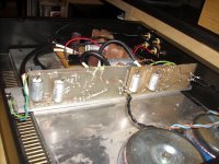
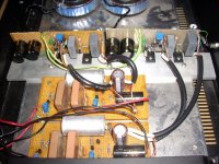
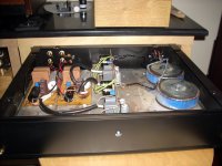
Ooops! I had pics from another 1.2 build for simplistic phono in my email box and forgot to see. Its about double mono 36V V1.2 with IRFP9240s this time. Like the first single rail CCT in page #190. Made by member Mikvous. You can see the application of coax on sense and force (Mogami stage monitor speaker pure copper thick coax). Also bypasses of Teflon FT-1 CCCP NOS on the main film caps. Mikvous said no practical problems he had, and also found nice subjective performance. He substituted V1.0s. Thanks Michael.
Ooops! I had pics from another 1.2 build for simplistic phono in my email box and forgot to see. Its about double mono 36V V1.2 with IRFP9240s this time. Like the first single rail CCT in page #190. Made by member Mikvous. You can see the application of coax on sense and force (Mogami stage monitor speaker pure copper thick coax). Also bypasses of Teflon FT-1 CCCP NOS on the main film caps. Mikvous said no practical problems he had, and also found nice subjective performance. He substituted V1.0s. Thanks Michael.
Attachments
Hello Nick,
I've lost something:
what do you meen with "the application of coax on sense and force "?
You explain in a precedent post?
Ciao
Guglielmo
I've lost something:
what do you meen with "the application of coax on sense and force "?
You explain in a precedent post?
Ciao
Guglielmo
Hi Guglielmo
In V1.2 circuits, the sense wiring should be carried with a coaxial shielded cable. Else noise will never be really zero in very high frequencies beyond audio. Mikvous had thick coax so he used it for the main force wiring too. If his phono was originally made with 1.2s in mind, he would probably had +/gnd near so not to expose the edges so much. But 1.2s are a recent months project.
In V1.2 circuits, the sense wiring should be carried with a coaxial shielded cable. Else noise will never be really zero in very high frequencies beyond audio. Mikvous had thick coax so he used it for the main force wiring too. If his phono was originally made with 1.2s in mind, he would probably had +/gnd near so not to expose the edges so much. But 1.2s are a recent months project.
Salas,
With guglielmo's question, I guess we need to sort out the exact meaning of the terminologies first. Does "force" refer to the rail? Does "sense" refer to the "rail sense"?
There are two sense wires - the rail sense and the ground sense. I think the rail sense needs to be shielded, but the ground sense needs not, because with the later the voltage potential is near 0 and the impedance is very low. The rail wire may be shielded, but it has pros and cons. Shielding reduces EMI pick-up, but the price to pay is that shielded cables have thin core which increases resistance and a little bit of inductance.
Correct me if I am wrong.
Regards,
Bill
- Status
- Not open for further replies.
- Home
- Amplifiers
- Power Supplies
- The simplistic Salas low voltage shunt regulator