Sense wire
How will have to do with the schematic of version V1.1 for Low MC Phono to became "sense wire".
How will have to do with the schematic of version V1.1 for Low MC Phono to became "sense wire".
Do you mean v1? There are schematics and discussions in the earlier part of this thread, possibly 1/4th from the beginning? If v1.1, there would be no difference from v1.2 as far as sense wires are concerned.
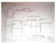
If you refer to the "Universal Simplistic Phono Shunt 2009", at the "Sense +" node belong C2-R7-Q2 and at the "Sense -" node R5-Q3
Connect also Q7 collector close to Q4 Source and R8 close to Q4 Drain
Connect also Q7 collector close to Q4 Source and R8 close to Q4 Drain
How will have to do with the schematic of version V1.1 for Low MC Phono to became "sense wire".
You mean how you can remote sense any V1.0 I guess. Forget V1.1 when there is 1.2. It was an intermediate step. Here is an example of your 46V V1.0 for Low MC for how to apply sense wiring. That is for just any V1.0 who somebody wants to apply sense wiring. V1.0 is not picking up noise from the sense wiring as easily and it can be done with a twisted pair, same type as the main output force wiring taken from Q4/C4 nodes.
Attachments

On second thought, use R1 = 22R or 15R 2-5W for 140-190mA its more conservative at 40-50V area for dissipation. Its the same circuit slightly better set for heat. Download and print that one with remote to make as it is. How is your phono build going along?
Load ground goes to star ground too, with main force wire 2. Repeat with a clean head and check for destroyed components if it will not work again. Will be happy to see your photos and tunings in the phono thread.
Make V1.0 remote that you have almost ready which is very good, simpler to layout and does not need the expert DIY oscope checks for reactions with loads, also is friendlier with RF pick up and GND, so to listen first, it matches very well with the phono. You can concentrate in a V1.2 build later on, when more expert, so to compare the resolution also.
Ok, to learn more, first of all I will do V1.0 without "sense wire" after when is operating I will try V1.0 with "sense wire" & finally with I am lucky will try the V1.2.
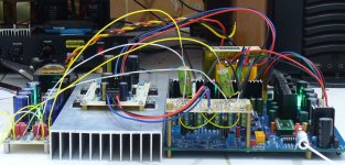
When operate I will post some pics in the phono thread.
When operate I will post some pics in the phono thread.
Well one reg. is going on but give max. 48V3 min. 48V2 using the 4k7 trimmer pot & leds aren't shining. I'm using a 150 ohms 10 watts resistor as load but the resistors is so hot that solder is fusing😡
mr. mago, point to the schematic you implemented and which particular Vin and current limit you chose.
You have some burned out components there.
I have changed Q2 2N5457 due to be burned, also I changed only to be sure both IRFP9140.
mr. mago, point to the schematic you implemented and which particular Vin and current limit you chose.
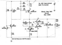
Is for Salas Simplistic Low MC Phono, Vin 55V Vout 45V current more or less 200mA.
Attachments
Last edited:
I have Vin 63V7 rectified & filtered before the reg., I am using a Tx 40V 1.2A.
I'm afraid for the filter cap, is rated 63V
I'm afraid for the filter cap, is rated 63V
Last edited:
Use a 10R 10W R input to your main filter cap. Will go down some Volt if the CCS operates.
Is your Ref a 4k7 resistor in line with a 4k7 to 5k trimmer as designated?
Is the Leds CCS correct for connections? Its a bit tricky there. The CCT you make works nicely fore some months now in symmetric for a D1 DAC BTW, made by CRT. So it will work in the end for you too, don't worry.
Is your Ref a 4k7 resistor in line with a 4k7 to 5k trimmer as designated?
Is the Leds CCS correct for connections? Its a bit tricky there. The CCT you make works nicely fore some months now in symmetric for a D1 DAC BTW, made by CRT. So it will work in the end for you too, don't worry.
Attachments
- Status
- Not open for further replies.
- Home
- Amplifiers
- Power Supplies
- The simplistic Salas low voltage shunt regulator