

Top secret documents from an encounter of the third kind with alien intelligence from the world of SPIKO have been obtained and are called for immediate public release. As these facts are too shocking, the reader discretion is advised.
HI-SCI-FI Productions bring you the all discrete shunt regulator v2d.
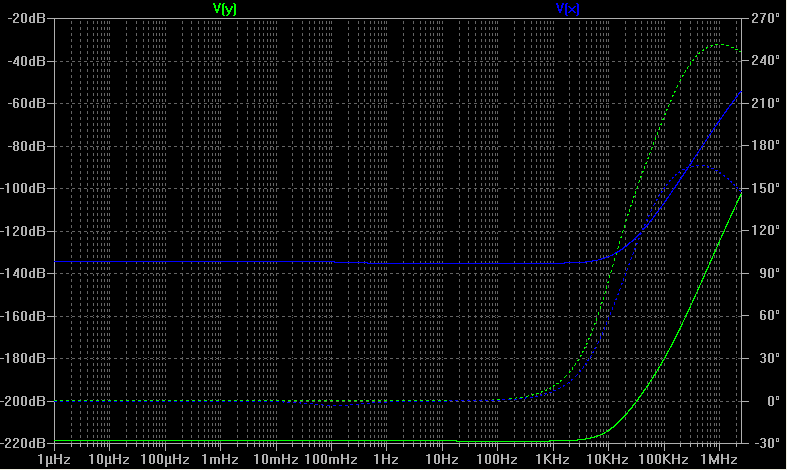
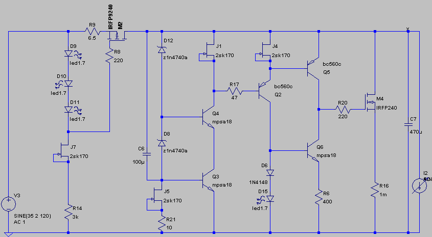
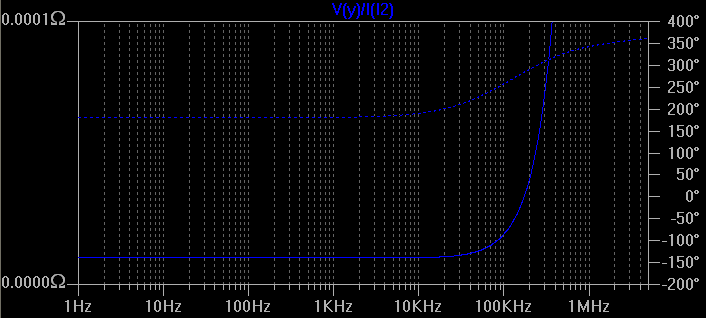
The unmatched psrr, as compared to v1 (green v2d, blue v1).
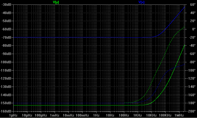
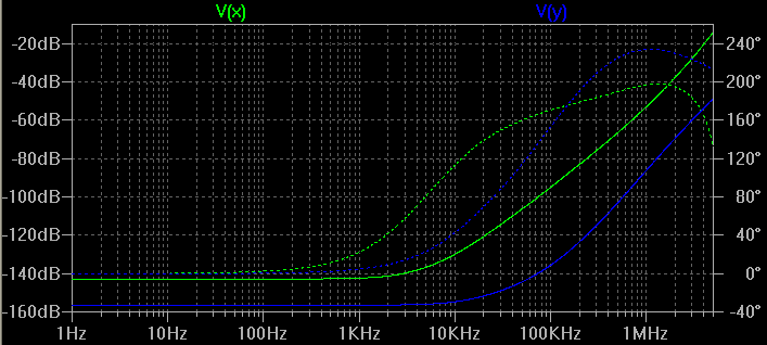
Shocking output impedance, too small to measure without a quantum o-sci-fi-lloscope TM, first shown in db.
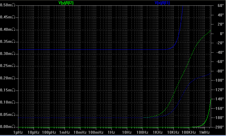
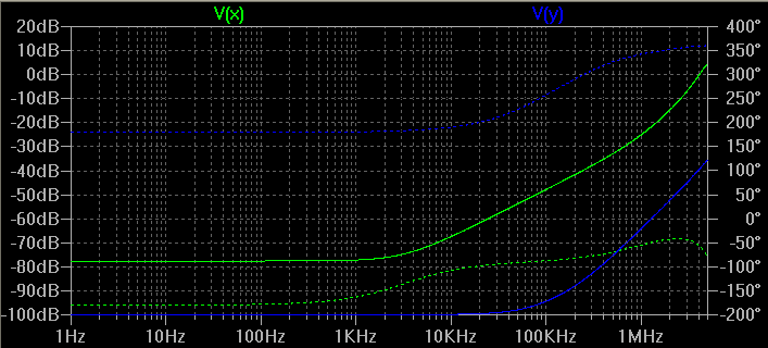
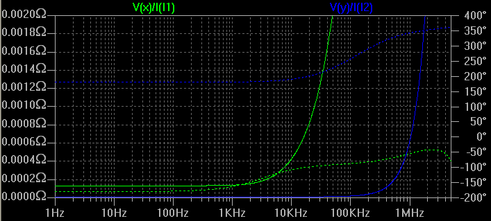
And also in ohms, next to v2d
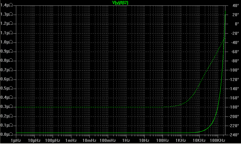
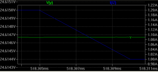
And also alone, measured at below 25 nanoOhms across most of the frequency range of interest.
And the circuit, 2009 (c) ikoflexer
Due to its unstable quantum state, do not attempt this at home unless you can get a hold of a few stabilizing salasion particles. However, alien diplomats have promised one case of Canadian beer sent to your door if you can get a stable version of similar performance without employment of said particles.
Disclaimer: no animals have been harmed in these simulated experiments, except, perhaps, for a certain cat belonging to one named Schroedinger, and that was way back in 1935.
😀 Funny introduction style Iko. I like it. 😀
Will you attempt to make it? Of course after the superconductive pcb and cables will be delivered from planet Krypton.
Will you attempt to make it? Of course after the superconductive pcb and cables will be delivered from planet Krypton.
Jam, at this level of psrr performance that capacitor has no effect.
salas, you started with the funnies, what can I say 😀
salas, you started with the funnies, what can I say 😀
jam said:Iko,
What happened to the capacitor at the junction of J& and R14?
Jam
What happened to the compensation cap !!
Hey, I'm not up with all this funky talk... 😀
Iko, does that version just above work fine, or is it unstable? I'm a bit thick... 😉
Cheers
Stuey
Iko, does that version just above work fine, or is it unstable? I'm a bit thick... 😉
Cheers
Stuey
Sorry guys, the circuit is not a lie, but it is meant as a joke. It's a real circuit in the sense that in simulation you get this amazing performance, but in reality I don't think it can be made stable.
Here's a challenge to all of you. If anyone can make it not oscillate and maintain any semblance of the shown performance above, you will get a case of beer delivered to your door, where ever you are.
Mike, what you call the compensation cap was used before because it improved a bit the psrr performance ( no effect on output impedance); but this circuit does not need it.
So, let me make it clear, I do not intend to build this because I do not believe it can be made stable. The loop gain is through the roof! 🙂

I mean't the miller type cap - but perhaps it's not necessary unless someone intends to build it 🙂
Stuey, you were spot on.
I don't know Jam, whatever the winner wants 😀
Oh I see Mike, you were talking about the high freq compensation cap. No amount of compensation could deal with this kind of loop gain, I think.
I don't know Jam, whatever the winner wants 😀
Oh I see Mike, you were talking about the high freq compensation cap. No amount of compensation could deal with this kind of loop gain, I think.
Hey guys, I have a question. Does any of you have some experience with DACs, in terms of what kind of load it presents to a power supply? Is it fairly steady, or is it varying, and if so, roughly how many mA would it jump around, and what what frequencies. Any pointers are appreciated! Thanks.
Basically I'm trying to assess if a regulator with a flat low output impedance up to around 200kHz would benefit DACs.
Edit: typo and clarification.
Basically I'm trying to assess if a regulator with a flat low output impedance up to around 200kHz would benefit DACs.
Edit: typo and clarification.
It would be very different for every chip's principle of conversion and other design peculiarities I suppose.
Such a question will have stronger chances of being thoroughly covered in the digital forum.
My mind first goes to provision for a very low noise Vref in the shunt, especially when the loop gain is high. And very good decoupling at the chip.
Such a question will have stronger chances of being thoroughly covered in the digital forum.
My mind first goes to provision for a very low noise Vref in the shunt, especially when the loop gain is high. And very good decoupling at the chip.
Thank you salas. Hmmm, I guess I thought about DACs because of some vague recollection about them requiring a stiffer psu in the higher frequencies. Was only trying to find a motivation for developing a wider bandwidth regulator, I mean, a practical motivation, as opposed to a theoretical one. Do you think there is any particular application that would benefit from flat low output impedance up to, say, 100 or 200kHz?
Edit: yes, I agree, but a quiet Vref is generally wanted and it affects everybody, I guess. Maybe even more a phono stage?
Edit: yes, I agree, but a quiet Vref is generally wanted and it affects everybody, I guess. Maybe even more a phono stage?
I think that it is most useful for a DAC, considering the dynamic range it can reach. A phono stage can give us an excellent low noise background if everything is designed and executed towards such a goal, but vinyl on a TT will not surpass 70dB as a source.
If you consider that wide bandwidth of keeping up the psrr and low output impedance in a reg will require strong gain, Vref considerations are rendered even more central.
I too know that density dacs work very fast, so your idea seems right to me. But I know from experience that I can not be certain since dacs are not something I know much of. There will be peculiarities for any chip.
I would put the question at the digital section of DIY audio.
OK, I think I may owe myself that case of beer. I know you guys are all tired of my ramblings, but hopefully it will end with this version. I will build it soon and hopefully it will be as stable in reality as it is in simulation. The design simulates as follows. V(x) is v1, V👍 is v2e. Dashed lines depict the phase.
PSRR
Output impedance in db
Output impedance of both v1 and v2e
Output impedance of v2e, detail; top value on the X axis is 100uOhm.
The promising fact about this circuit is that the calculated phase margin is quite high, about 60 degrees, so, in theory, it should be stable. I plan to build a prototype and will post whatever results.
Here's the circuit. The parts need not be the same, but one must be careful with anything that might change the phase profile. The BD140 passes constantly about 75mA (1.5W); I chose a load of 100mA and the shunt passes about 137mA. The shunt mosfet here is an irf510 because it's the smallest input capacitance mosfet I have on hand and want to try it out.
salas, do you remember when I first contacted you about your original shunt, and asked about driving the shunt mosfet with more current. It's a bit ironic to come full circle; if this works, then the simple solution was all along a higher loop gain and a strong buffer for the mosfet.
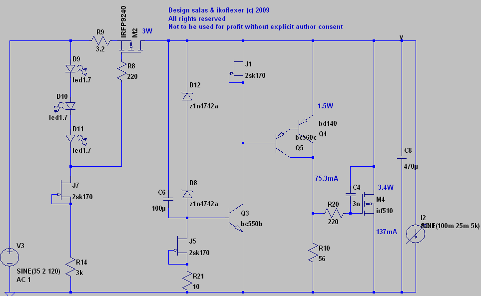
Any comments and suggestions would be appreciated.
PSRR
Output impedance in db
Output impedance of both v1 and v2e
Output impedance of v2e, detail; top value on the X axis is 100uOhm.
The promising fact about this circuit is that the calculated phase margin is quite high, about 60 degrees, so, in theory, it should be stable. I plan to build a prototype and will post whatever results.
Here's the circuit. The parts need not be the same, but one must be careful with anything that might change the phase profile. The BD140 passes constantly about 75mA (1.5W); I chose a load of 100mA and the shunt passes about 137mA. The shunt mosfet here is an irf510 because it's the smallest input capacitance mosfet I have on hand and want to try it out.
salas, do you remember when I first contacted you about your original shunt, and asked about driving the shunt mosfet with more current. It's a bit ironic to come full circle; if this works, then the simple solution was all along a higher loop gain and a strong buffer for the mosfet.
Any comments and suggestions would be appreciated.
Iko,
With all due respect I would leave out the mosfet and make the darlington (discreet) the shunt element......now that would be something worh simulating.😉
Jam
With all due respect I would leave out the mosfet and make the darlington (discreet) the shunt element......now that would be something worh simulating.😉
Jam
jam said:Iko,
With all due respect I would leave out the mosfet and make the darlington (discreet) the shunt element......now that would be something worh simulating.😉
Jam
Thanks Jam, it's a good idea which I've explored already. It does not do better though, but I might come back to it. And don't worry about making any suggestion, I welcome all input.
mikelm,
Hopefully, no-one will make that serious mistake. All you would get is a lot of headaches.I mean't the miller type cap - but perhaps it's not necessary unless someone intends to build it
Lumba Ogir said:mikelm,
Hopefully, no-one will make that serious mistake. All you would get is a lot of headaches.
Well, I too hope nobody's building that one; I explicitly said the circuit was a joke and it should not be built.
Now, this other one, may be another matter. I wouldn't mind a capable regulator for my chipamp.
Attachments
- Status
- Not open for further replies.
- Home
- Amplifiers
- Power Supplies
- The simplistic Salas low voltage shunt regulator