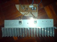
Salas, Vin is about 18.6V and Vout is 12.6V...I do not know whether the sink is big enough though. It measures something like 10" L
x 3" W x 2" high fins spaced at 0.5". Have been on most of today and it is hot to the touch. Do not know the temperature as I have nothing to measure it at the moment.
Soundwise, I hear more bass and the overall presentation is smoother overall. I think it will sound more transparent with more run in.
are you on a "keep fit" regime? Cycling, swimming, running or some other activity?Tham said:Running in now and will give it a listen soon 🙂 .
find the hottest part/s with you finger.Tham said:Have been on most of today and it is hot to the touch. Do not know the temperature as I have nothing to measure it at the moment.
How long can you keep your finger on the hottest part?
That becomes a very good indicator of acceptable heatsink temperature.
You don't need to measure the temperature accurately to make the circuit perform any better.
AndrewT said:are you on a "keep fit" regime? Cycling, swimming, running or some other activity?
Oh, come on Andrew, give him a break 😉
As Andrew said. BL grade, 7 to 9mA you will find enough in any batch.
Use 10R R1 if your leds are going to be 1.8 to 1.9V which is more common to find.
Use 10R R1 if your leds are going to be 1.8 to 1.9V which is more common to find.
Just to report that my T amp is singing now with Salas T amp shunt...stable up to now and music flow with ease that I have not heard before with my simple linear reg and smps.
Close to finishing a Iko's high current v1.5 too (still to find BFT92/BFR92 locally and may opt for 2N2222/4403 instead) and hope to be able to power it up this week.
🙂 .
Close to finishing a Iko's high current v1.5 too (still to find BFT92/BFR92 locally and may opt for 2N2222/4403 instead) and hope to be able to power it up this week.
🙂 .
Tham, don't forget the mpsa81/mpsa10 pair. Those are cheap and easy to find. I posted before that mpsa81/mpsa18 simulated well. The mpsa18 might be overkill as far as gain goes (might be less stable). You can just try the 2n2222a as well, and see practically which works better.
So you get better sound and you had a reg on it before, although series. That is good. The contrast is very strong from simple transformer, bridge and cap of course. 1.5 has to sound even better. I hope there will be no implications with more bandwidth. But try to see what is your optimum current in meantime for your given speakers and listening room/habits. Maybe by increasing by half Amper and listening. That will add further dissipation though. But you must know if it is superfluous or not. Did you make the Vbe controlled V1 which is more certain for predicting R1? Or the led controlled? What is the value of your R1 and the voltage across it? I would like to see a picture if you have. Congratulations. The shunt scales powerfully as you see, with no problems.
Hi Salas, do you mean increasing v1 current by half an ampare? For the v1 build is the non LED version with R1 at 0.27ohm (wirewound). Let me know how I can increase the current.
I did another measurement of Vin and Vout on load and it ise 16.5v & 12.6v respectively.
Will try to post a picture tomorrow.
AndrewT, the heatsink is very hot near the MOSFETs and barely touchable. I can touch the hottest part of the fin for few seconds though.
Found 2N2222A/2N4403 and completed my v1.5 build. Hope to have it tested tomorrow 🙂.
From your info I can safely calculate that you run around 2.4A right now, since Vbe is surely predictable. With a 0.22R it will go up to 3A but with what you say about your sink I am afraid it may overheat. My friend's runs 2.5A too for 8 Ohm FR8 Hemp in TQWT chamber and 3A wasn't needed as I have checked, so we put it back to save on heat.
Save the experiment to check on your speakers for later when you will have a bigger sink maybe. Good luck on V1.5, set it for 2.5A too if you plan to experiment on the same sink.
Save the experiment to check on your speakers for later when you will have a bigger sink maybe. Good luck on V1.5, set it for 2.5A too if you plan to experiment on the same sink.
if the edge of the fins are that hot then you are probably around 50 to 60degC.
Barely touchable at the hottest part is probably >=60degC.
Tc will be 5 to 10C above heatsink temp.
That seems to indicate that your device is probably running with Tc>70degC.
That is possibly too hot.
Much hotter than I would dare to run it.
Barely touchable at the hottest part is probably >=60degC.
Tc will be 5 to 10C above heatsink temp.
That seems to indicate that your device is probably running with Tc>70degC.
That is possibly too hot.
Much hotter than I would dare to run it.
 that is one hot property of Tham 😀
Best wishes with v1.5 Tham. At such high current, expect a really low impedance at high freq too, watch out for oscillation. Let me know when you'll try it so I may help.
Iko, with R1 is at 0.1ohm. Am I right to say that I should set the voltage across it to 250mV for 2.5A with the shunt connected to my T amp? I have a 1K trimmer as Rset and hope it is not a problem.
Tham said:Iko, with R1 is at 0.1ohm. Am I right to say that I should set the voltage across it to 250mV for 2.5A with the shunt connected to my T amp? I have a 1K trimmer as Rset and hope it is not a problem.
If you measure a voltage drop of 250mV across a resistor of 0R1, then yes, there is 2.5A current passing through.
For Rset, you better start with it set at a small value; that translates into a small Vgs; then increase Rset until you see the current over R1 increases.
- Status
- Not open for further replies.
- Home
- Amplifiers
- Power Supplies
- The simplistic Salas low voltage shunt regulator